ASSA ABLOY ACCENTRA 633F Trim Installation Instructions_80-8470-0633-000
Open the original PDF document
View PDF633F
Exit Device Trim
Installation Instructions
Cylinder locks/ unlock thumbpiece. F05 (as packed), key removable with trim locked or unlocked. F06 (fi eld conversion), key removable only when trim is locked.

This product can expose you to lead which is known to the state of California to cause cancer and birth defects or other reproductive harm. For more information go to www.P65warnings.ca.gov.
WARNING
Attention Installer: Any retrofi t or other fi eld modifi cation to a fi re rated opening can potentially impact the fi re rating of the opening, and ASSA ABLOY makes no representations or warranties concerning what such impact may be in any specifi c situation. When retrofi tting any portion of an existing fi re-rated opening, or specifying and installing a new fi re-rated opening, please consult with a code specialist or local code offi cial (Authority Having Jurisdiction) to ensure compliance with all applicable codes and ratings.
80-8470-0633-000 04/24
633F
Exit Device Trim Installation Instructions
1. Assembly
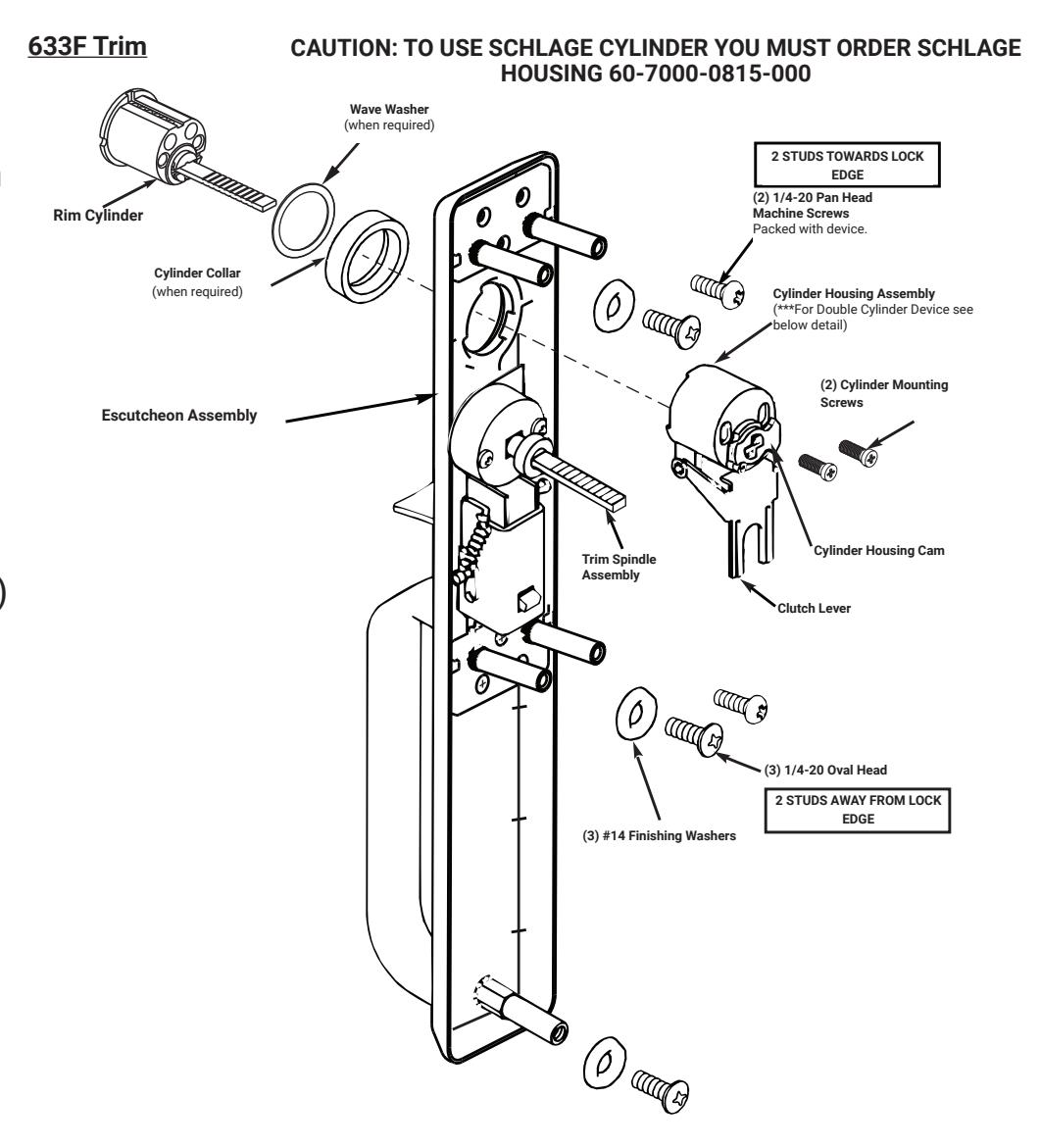
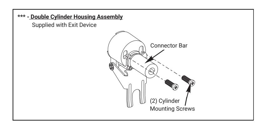
- 1. Check cylinder components. Non-standard cylinder collars and mounting screws must be supplied with optional cylinders.
- 2. Assemble cylinder. Insert cylinder housing prongs into escutcheon matching notches. Pass cylinder tailpiece thru cylinder collar and cylinder housing slot in cam. Bolt cylinder seated in cylinder collar recess (DO NOT OVERTIGHTEN SCREWS).
- 3. Check cylinder action. Cylinder must freely rotate tailpiece into lock (cam pushing locking lever down) and unlock (shown) positions. When locking lever is engaged, it depresses the trim spindle. The thumbpiece handle is, thus disengaged from the spindle.
- 4. Cut cylinder tailpiece. Correct length is 1/16" to 3/16" (2 to 5mm) beyond cylinder housing cam.
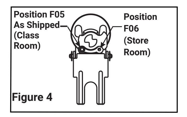
- 5. Determine trim function. See Figure 4
F05: As shipped. Key locks/unlocks thumbpiece handle. Key removable in lock and unlock position.
F06: Field move function screw to hole in cylinder housing under cam tip. Key locks/unlocks thumbpiece handle. Key removable ONLY in lock position.
633F
Exit Device Trim Installation Instructions
2. Installation
- 1. Check box for components.
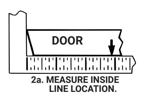
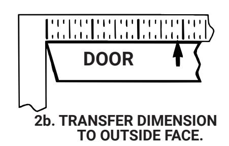
- 2. After marking door inside face for device location (Device Instructions), carry " Vertical Reference Centerline" from inside door face. Follow steps 2a. and 2b., shown to the right
- 3. Transfer Horizontal Reference Centerline from inside to outside door face.
- 4. Align trim template and tape to outside door face.
- 5. Spot holes and prepare door for trim
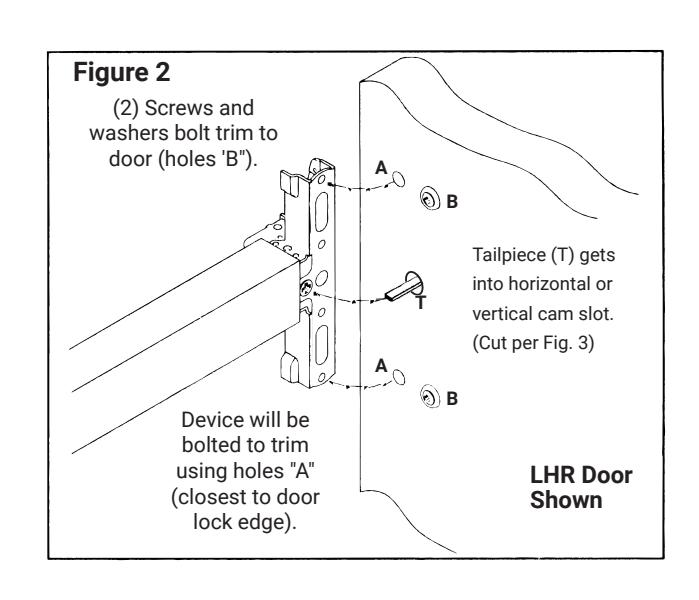
- 6. Mount trim to door thru holes "A" with (2) mounting screws as shown in Fig. 2. Use the remaining (3) oval headed screws and fi nish washers to secure the trim to the door surface through location "B" as shown in Fig. 2, the third screw and washer attaches to the hole located at the bottom of the trim.
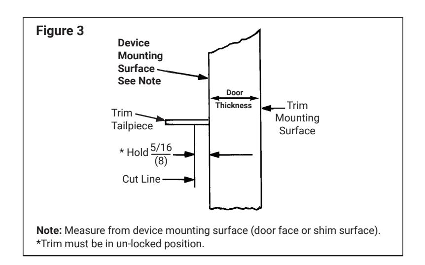
- 7. With trim unlocked (tailpiece turning when thumbpiece is depressed) cut trim tailpiece as shown in Fig. 3.
- 8. Seat device so that the trim tailpiece penetrates cam slot as shown in Fig. 2. Continue as shown in device instructions.
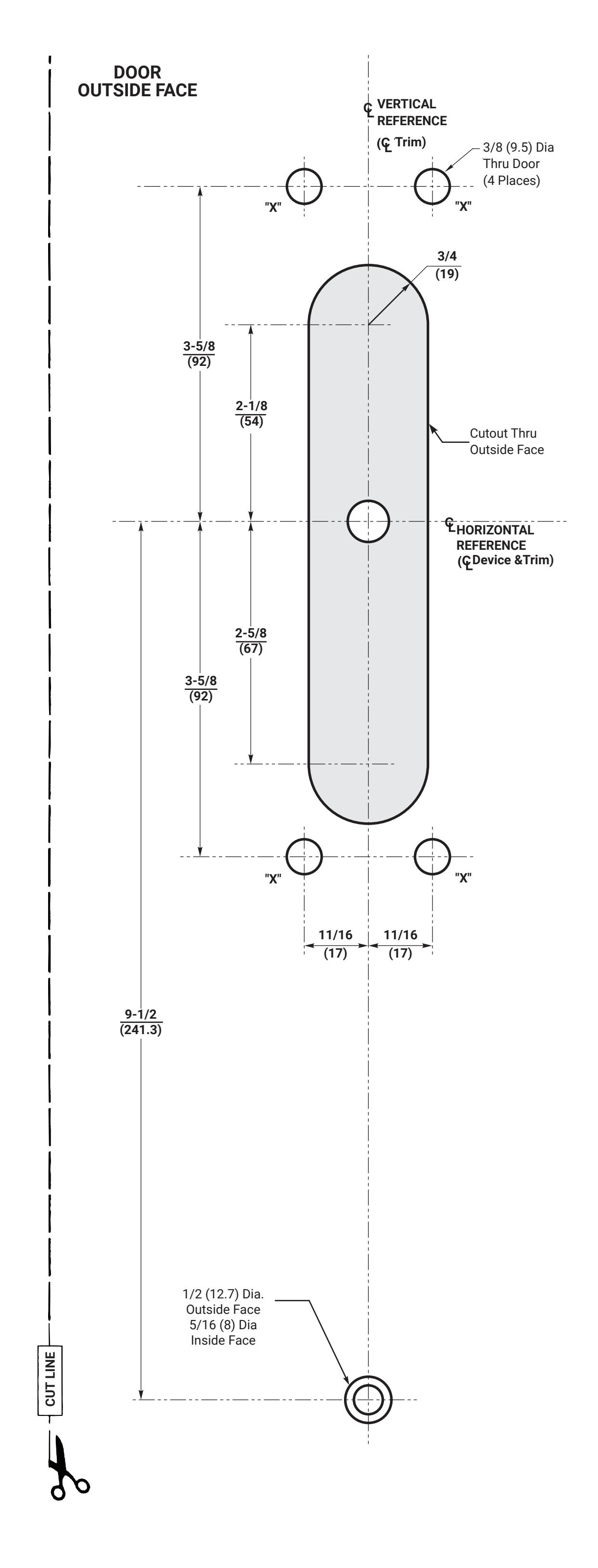
633F Trim Template
CAUTION: Offi ce copiers and facsimile machines may change the size of a drawing and make the template inaccurate to use as a door marker. If this is not the original template packed with the trim, use only the holes on the door (do not use template as a door marker).
Dimensions given in inches (mm) .