ASSA ABLOY ACCENTRA 6170LBR, 6170LBR-10, 6170F90-LBR, 6170F90-10LBR, 6175LBR, 6175LBR-10, 7170LBR_7470-0075
Open the original PDF document
View PDF
Notes:
- 1. Do not scale drawing.
- 2. Dimensions are in inches (mm).
- LHR door shown. Preparation is typical for both door hands
- 4. Minimum door stile width 4-1/2(114).
- 5. Prepare mounting holes when installing the device.
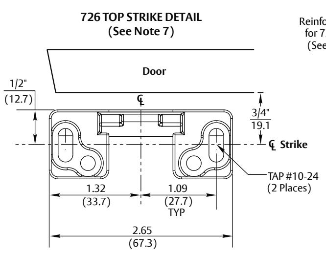
- 6. Unreinforced frames require blind rivet nuts (by others) to mount the strike.
- 7. Door in frame with door silencers. Compensate strike distances for other conditions.
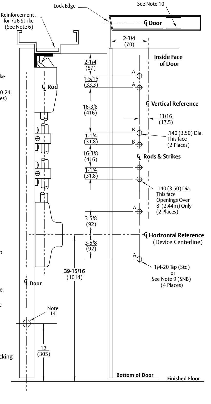
- 8. For recommended door reinforcements see template 7400-0000. Unreinforced doors require SNB option to mount the device components.
- 9. Holes for optional SNB: 9/32 (7.00) dia. inside door face; 3/8 (9.50) dia. outside door face.
- Provide door stiffeners, as needed to prevent door collapse due to installation with power tools, door use, or abuse.
- 11. Device mount to hinge stile (not shown) requires hole location and preparation during device installation.
- 12. For outside trim preparation see appropriate trim template.
- 13. For electrical devices (suffixes "-B","-G","-O","-P","-S") also see template 7477-0001.
- 14. Door structure as required for heat activated interlocking bolt. See template 7470-1700.
RESPONSIBILITY
DOOR AND FRAME MANUFACTURERS ARE RESPONSIBLE FOR PROVIDING ADEQUATE CONSTRUCTION OR REINFORCEMENTS FOR PROPER INSTALLATION OF HARDWARE SHOWN. ALL ARCHITECTURAL BUILDERS HARDWARE MUST BE INSTALLED ON PROPERLY REINFORCED DOORS AND FRAMES, REGARDLESS OF TYPE, MATERIAL, OR METHOD OF CONSTRUCTION.
6170LBR, 6170LBR-10, 6170F90-LBR, 6170F90-10LBR, 6175LBR, 6175LBR-10 7170LBR, 7170LBR-10, 7170F90-LBR, 7170F90-10LBR, 7175LBR, & 7175LBR-10 Surface Vertical Rod Exit Devices For Metal Door and Frame Application Less Bottom Rod; 726 Top Strike
Contact us for support at 1-855-577-5078.
ASSA ABLOY
SUPERSEDES DO NOT SCALE DRAWING TEMPLATE NUMBER 7470-0075 DATE 01-24