ASSA ABLOY ACCENTRA 6160(F90)LBR, 7160(F90)LBR, 6165LBR(-10) & 7165LBR(-10) Wide Stile CVR 761 Top_7470-1065
Open the original PDF document
View PDFFOR NOTES & FRAME PREP SEE SHEET 2 1-7/8 1-7/8 (48)(48) DOOR SPECIFICATION 5/16 1-1/81-1/8 5/16 Door Thickness: 1-3/4" (7.9)(29)(29)(7.9)7/16 (45mm) Min. (11.1)Ф Door Construction: Wood or composite door with Latch fire or panic rating as required. Door may require A metal channel edge which may alter backset 0 7/8 dimensions. Consult door manufacturers listings. (22.2)7/8 .173 (4.40) x Exit Device Ratings: 1 (25) Deep (22.2)6160-LBR, 6165-LBR, (6 Holes on Door Top 7160-LBR, 7165-LBR, & 6 Holes on Bottom) 3-3/4 Panic Exit Door up to 4' x 8' (95)Cutout 3/8 (10)6160F90-LBR, 7160F90-LBR, 90 Minutes rated Fire Exit Door up to 4' x 8' INSIDE FACE 7/8 4-1/2 1/4 5/8 1-1/2OF DOOR (22)6160-LBR-10, 6165-LBR-10., (16)(3.8)(114)(6)1-7/16 11/16 7-LBR-10, 160 7165-LBR-10, (36.5) (17.5)Panic Exit Door up to 4' x 10' <u>1/2</u>Thru Door Lockstile (25) (13)Vertical Reference 7/8 3/8 (9.50)R Typ. (22)(2 Slots, This Face) 3-5/8 Rods, Strikes & Cutouts (92)(51)4 Horizontal Reference (51) 6-1/2 3-5/8 € Door (165)9/16 (16)7/8 3/8 (9.50) (22)Thru Door (2 Places) 39-15/16 (1014)See Note_12 (305) Finished Floor 1/4(6) Recommended 3/4(Maximum)
RESPONSIBILITY
DOOR AND FRAME MANUFACTURERS ARE RESPONSIBLE FOR PROVIDING ADEQUATE CONSTRUCTION OR REINFORCEMENTS FOR PROPER INSTALLATION OF HARDWARE SHOWN. ALL ARCHITECTURAL BUILDERS HARDWARE MUST BE INSTALLED ON PROPERLY REINFORCED DOORS AND FRAMES, REGARDLESS OF TYPE, MATERIAL, OR METHOD OF CONSTRUCTION.
6160(F90)LBR, 7160(F90)LBR, 6165LBR(-10) & 7165LBR(-10)
Concealed Vertical Rod Exit Devices
Application for Wood Door & Metal Frame Less Bottom Rod; 761 Top Strike
Contact us for support at 1-855-557-5078.
ASSA ABLOY
SUPERSEDES 12/16 DO NOT SCALE DRAWING TEMPLATE NUMBER 7470-1065 SHEET 1 of 2 DATE 12-23
761 Top Strike Preparation (See Note 6)
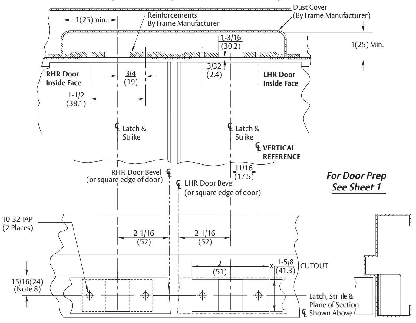
NOTES:
- 1. Do not scale drawing.
- 2. Dimensions are in inches (mm).
- 3. Preparation is typical for both hands.
- 4. Minimum door stile width: 4-1/2 (114).
- 5. Prepare mounting holes when installing the device.
- 6.Drawing shows elevation (frame bisected on strikecenter), bottom view looking up and side view.
- 7. Provide adequate structural support to maintain door integrity after device installation with power tools, door use, or abuse.
- 8. Door located in frame for door silencers. If not used, compensate this dimension to seat the door against the stop without rattle.
- 9. Device mount to hinge stile (not shown) requires hole location and preparation during device installation. Door structural requirements are similar for both stiles.
- 10. For outside trim preparation see appropriate trim template.
- 11. For electrical devices (suffixes "-B", "-G", "-O", "-P", "-S") also see template 7477-0001.
- 12. For labeled door pairs only. Reinforce door as needed for heat activated interlocking bolt. See template 7470-1700.
- 13. Door structure as required for heat activated interlocking bolt. 1-1/2 square 16 ga. plate recommended.
RESPONSIBILITY
DOOR AND FRAME MANUFACTURERS ARE RESPONSIBLE FOR PROVIDING ADEQUATE CONSTRUCTION OR REINFORCEMENTS FOR PROPER INSTALLATION OF HARDWARE SHOWN. ALL ARCHITECTURAL BUILDERS HARDWARE MUST BE INSTALLED ON PROPERLY REINFORCED DOORS AND FRAMES, REGARDLESS OF TYPE,
6160(F90)LBR, 7160(F90)LBR, 6165LBR(-10) & 7165LBR(-10)
Concealed Vertical Rod Exit Devices
Application for Wood Door & Metal Frame Less Bottom Rod; 761 Top Strike
MATERIAL, OR METHOD OF CONSTRUCTION. Contact us for support at 1-855-557-5078.
7470-1065 2 of 2 SHEET DATE SUPERSEDES DO NOT SCALE DRAWING TEMPLATE NUMBER 12/16 12-23