ASSA ABLOY ACCENTRA 615 Cylinder Dogging Kit Installation Instructions_80-9460-6018-000
Open the original PDF document
View PDF615 Cylinder Dogging Kit
ASSA ABLOY
Exit Devices
Installation Instructions
Application
Any Non-Fire Rated 6000 Series Exit Devices (Rim, Vertical Rod, or Mortise)
Important: Installation in any Fire Exit Device (6100F and 6200F Series) is prohibited and violates national and/or local life safety and building codes. Application to fire labeled exit devices cancels the Underwriters Laboratories label.
Note:
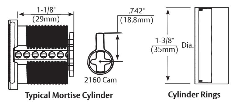
- Use ASSA ABLOY® 2153 x 2160 cam, 1-1/8" (29mm) mortise cylinder (order separately). For cylinders over 1-1/8" (29mm), use cylinder ring.
- All dimensions listed are in inches ( " ) and millimeters (mm).
⚠ WARNING
This product can expose you to lead which is known to the state of California to cause cancer and birth defects or other reproductive harm. For more information go to www.P65warnings.ca.gov.
MARNING
Attention Installer: Any retrofit or other field modification to a fire rated opening can potentially impact the fire rating of the opening, and ASSA ABLOY makes no representations or warranties concerning what such impact may be in any specific situation. When retrofitting any portion of an existing fire-rated opening, or specifying and installing a new fire-rated opening, please consult with a code specialist or local code official (Authority Having Jurisdiction) to ensure compliance with all applicable codes and ratings.
80-9460-6018-000 10/23
ASSA ABLOY
615 Cylinder Dogging Kit Exit Devices
Installation Instructions
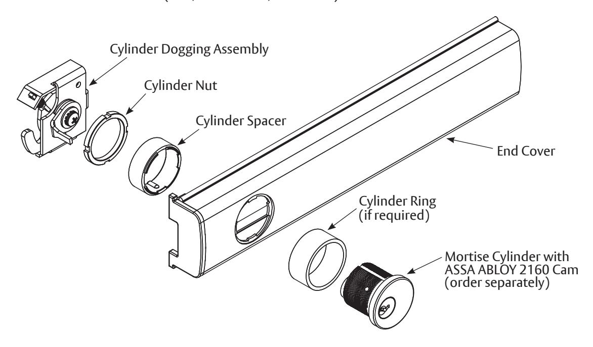
A. Cylinder End Cover Assembly
- 1. Position cylinder into new end cover with keyway horizontal.
- 2. Engage cylinder spacer lugs into matching notches in end cover.
- 3. Secure parts in place with cylinder nut.
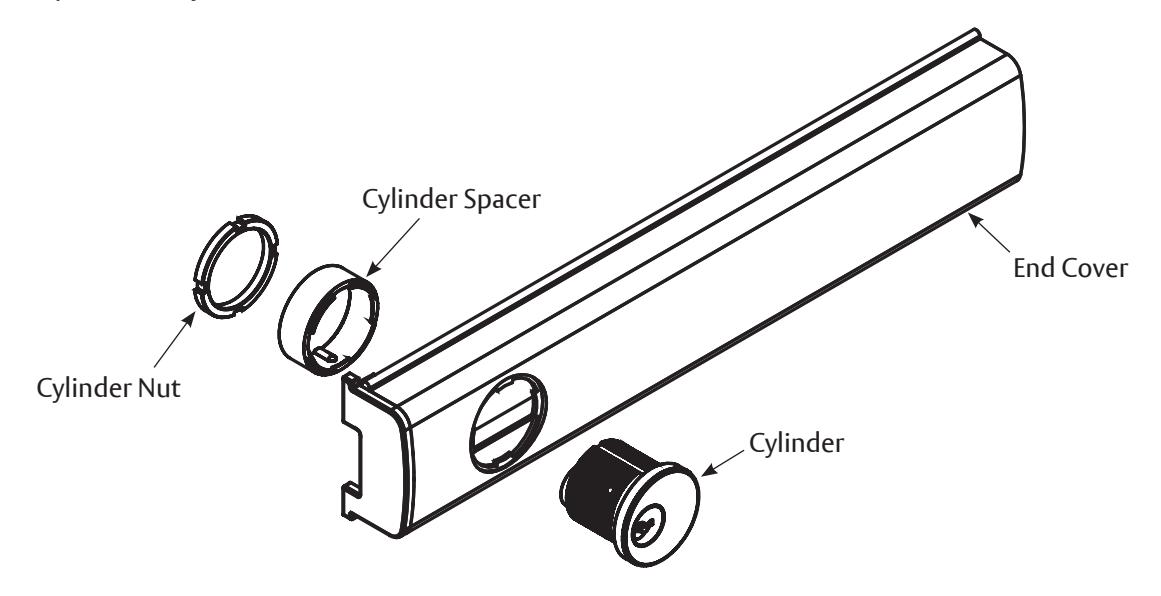
Figure 1: End Cover Assembly
B. Removal of Standard Dogging Assembly
Note: Retain all parts until instructions are complete.
- 1. Remove end cap from exit device by removing one (1) #10-24 x 1/2" (13mm) Phillips Round Head Machine Screw (PRHMS).
- 2. Slide original end cover off.
- 3. Remove standard (hex-key) dogging assembly by removing two (2) #8-32 x 3/4" (19mm) Phillips Flat Head Taptite Machine Screws (PFHTTMS).
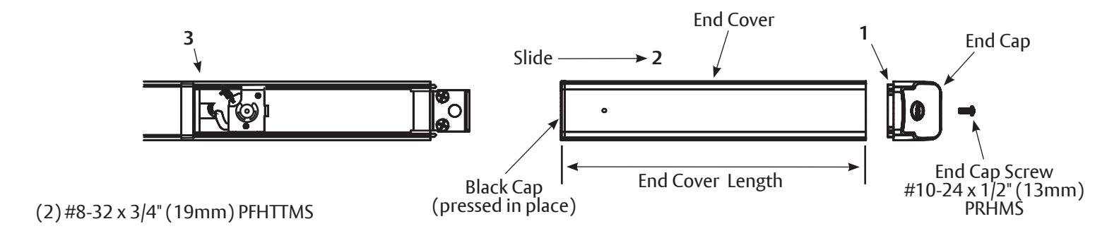
Figure 2: Device with Standard Dogging
615 Cylinder Dogging Kit
Exit Devices
Installation Instructions
ASSA ABLOY
C. Installation of Cylinder Dogging Assembly
- 1. Install cylinder dogging assembly, positioned as shown. Use two (2) #8-32 x 3/4" (19mm) PFHTTMS screws provided.
- 2. Cut new end cover, if necessary, on end furthest from cylinder hole.
- 3. Slide end cover assembly in place.
- 4. Replace end cap from step B with one (1) #10-24 x 1/2" (13mm) PRHMS.
-
5. Check cylinder dogging action.
- To engage, fully depress touchbar, turn dogging cylinder key clockwise (latchbolt should be fully retracted and touchbar should remain fully depressed).
- To disengage, turn dogging key counterclockwise, while keeping touchbar fully depressed (touchbar and latchbolt should become active).
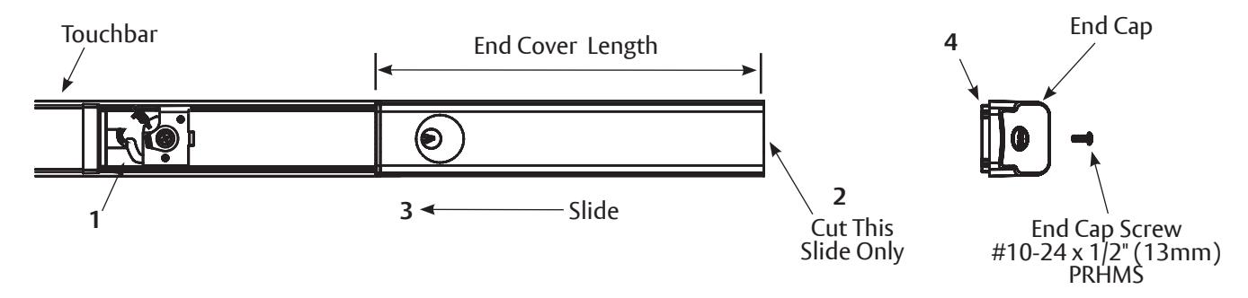
Figure 3: Device with Cylinder Dogging