ASSA ABLOY ACCENTRA 6130(F), 6135, 7130(F), 7135 Wide Stile Mortise ANSI A115.1 Strike Pair of Metal_7470-0031
Open the original PDF document
View PDF
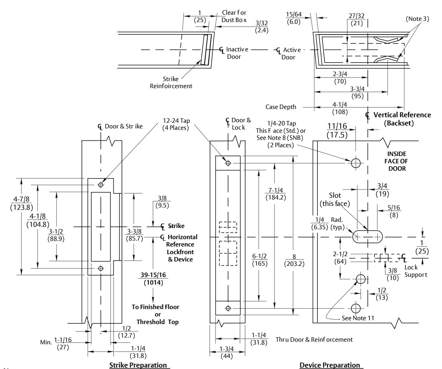
Notes:
- 1. Minumum Stile Width 4-1/2 (114).
- 2. For door reinforcements see template 7400-0000. Unreinforced doors require optional SNB to mount devices.
- Unless otherwise specified, door preparation and dimensional tolerences must conform to ANSI A115.1. Lock support required as shown.
- 4. For outside trim preparation see appropriate trim template.
- 5. Prepare mounting holes when installing the device.
- 6. LHR active pair shown. Preparation is typical for both door hands.
- 7. Dimensions are in inches (mm). Do not scale drawing.
- 8. Holes for optional SNB: 9/32 (7.00) Dia. inside door face 3/8 (9.50) Dia. outside door face.
- 9. Dimensions giv en about a center line are symmetr ical.
- 10. Device mount to hinge stile (not sho wn) requires holes location and preparation during device installation.
- 11. For Electrical device suffixes "-Safe", "-Secure", "-O-", or "-S-":1/2 (12.70) diameter, this face, plus prep shown on template 7477-0001.
- 12. For electrical device suffixes "-B", "-G", or "-P" also see template 7477-0001.
- 13. Latchbolt center line is 23/32 (18.2) below & Auxbolt centerline is 3/16 (4.8) above the centerline of lockfront.
RESPONSIBILITY
DOOR AND FRAME MANUFACTURERS ARE RESPONSIBLE FOR PROVIDING ADEQUATE CONSTRUCTION OR REINFORCEMENTS FOR PROPER INSTALLATION OF HARDWARE SHOWN. ALL ARCHITECTURAL BUILDERS HARDWARE MUST BE INSTALLED ON PROPERLY REINFORCED DOORS AND FRAMES, REGARDLESS OF TYPE, MATERIAL, OR METHOD OF CONSTRUCTION.
6130, 6135, 6130F, 7130, 7135 & 7130F Mortise Exit Devices with ANSI A115.1 Strike
Application for Pair of Metal Doors without Mullion
Contact us for support at 1-855-577-5078.
ASSA ABLOY
SUPERSEDES DO NOT SCALE DRAWING TEMPLATE NUMBER 7470-0031 DATE 01-24