ASSA ABLOY ACCENTRA 6116 Alarm Kit Installation for 6000 Series Exit Device Installation_80-9460-6011-000
Open the original PDF document
View PDFExit Alarm Kit 6116 Series Exit Devices
Installation Instructions
For use with all 6000 Series Exit Devices except Surface Vertical Rod
Note: This kit may be used to upgrade the Touchbar Alarm on the following product series:
- 6100F
- 6130F
- 6150F
- 6160F
- 6170F
- 6170F(WS)
- 6220
- 6250
WARNING
This product can expose you to lead which is known to the state of California to cause cancer and birth defects or other reproductive harm. For more information go to www.P65warnings.ca.gov.

WARNING
Attention Installer: Any retrofit or other field modification to a fire rated opening can potentially impact the fire rating of the opening, and ASSA ABLOY makes no representations or warranties concerning what such impact may be in any specific situation. When retrofitting any portion of an existing fire-rated opening, or specifying and installing a new fire-rated opening, please consult with a code specialist or local code official (Authority Having Jurisdiction) to ensure compliance with all applicable codes and ratings.
ASSA ABLOY
Exit Alarm Kit 6116 Series Exit Devices Installation Instructions
Table of Contents
| A. Verify Parts | 3 |
|---|---|
| B. 6116 Series Exit Alarm Kit - Exploded View | 3 |
| C. Remove Device Assembly | 4 |
| D. Remove Existing Cover | 4 |
| E. Activate and Test the New Alarm Assembly | 5 |
| F. Mounting the Switch Lever | 6 |
| G. Exit Bar Installation | 10 |
| H. Testing | 11 |
| I. Troubleshooting | 11 |
| I Maintenance | 11 |
| Acronym | Definition | |
|---|---|---|
| PPHMS | Phillips Pan Head Machine Screw | |
| PFHUMS | Phillips Flat Head Under Cut Machine Screw | |
| PFHWS | Phillips Flat Head Wood Screw | |
| PPHSMS | Phillips Pan Head Sheet Metal Screw | |
| PHPNHD | Phillips Pan Head Self Tapping Screw | |
Tools Required

Square Socket
Phillips Head
Pencil
Safety Glasses
Exit Alarm Kit
6116 Series Exit Devices
Installation Instructions
ASSA ABLOY
A. Verify Parts
- 1. Unpack and verify the components received using the parts list and the exploded view in Figure 1.
- 2. Read the entire instructions before installing this kit.
- 3. Follow all cautions, notes and warnings presented in these instructions.
- 4. All dimensions listed are in inches (") and millimeters (mm).
⚠ Important:
- Be sure to install the device on the correct door and confirm the device function, finish and size.
- Use site survey to verify the correct product was ordered.
- This product is intended to be a replacement alarm kit or an update for the Touchbar Exit Devices.
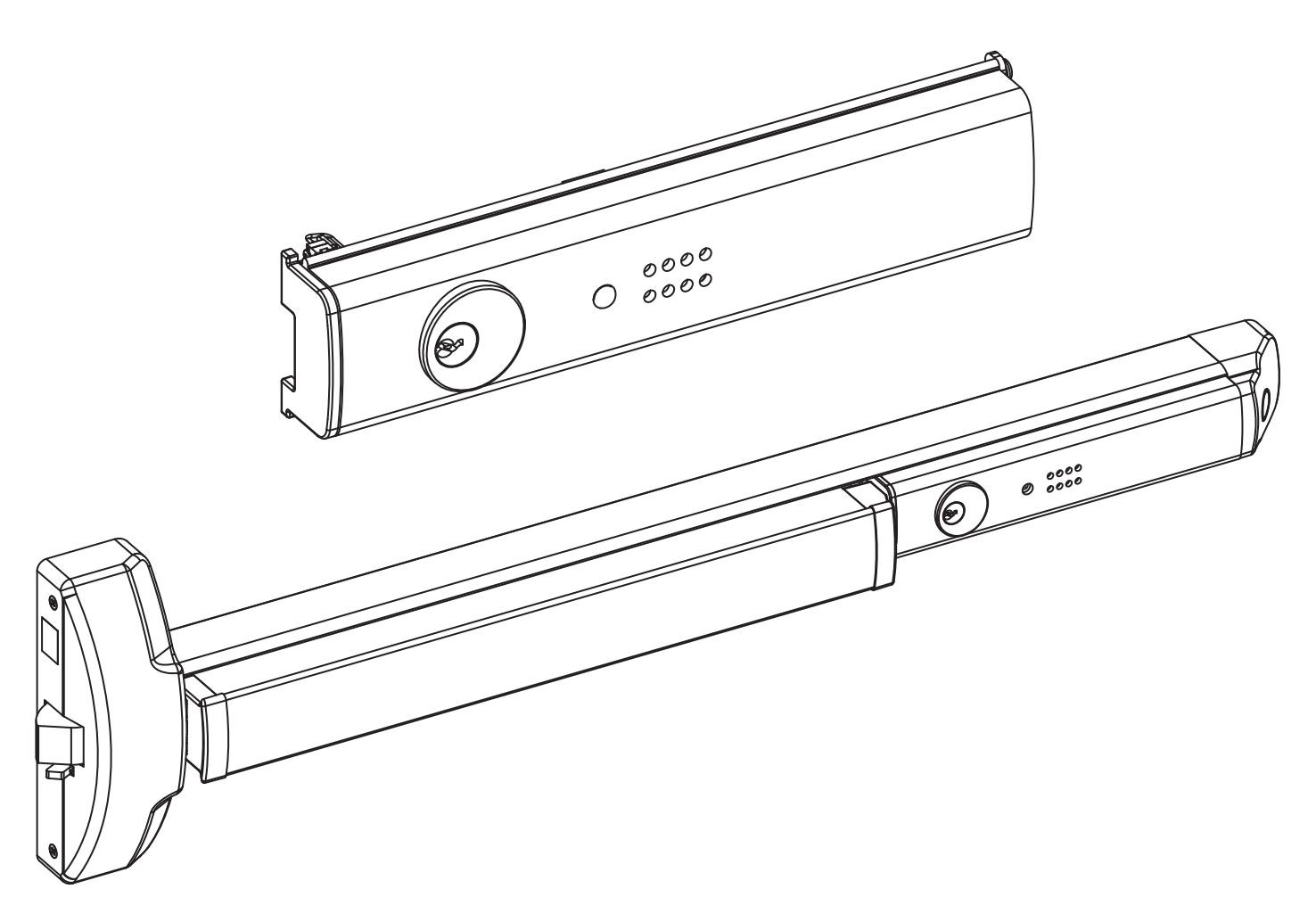
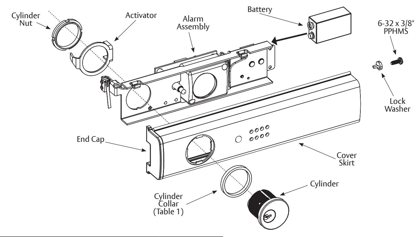
B. 6116 Series Exit Alarm Kit - Exploded View
The 6116 Series Exit Alarm Kit consists of the contents shown in Figure 1; additionally the kit requires a 9-Volt Battery which is not included, but is shown in the figure for placement.
Figure 1: Exploded View of the 6116 Series Exit Alarm Kit
|
Table 1:
Cylinder Collar Specifications |
||||
|---|---|---|---|---|
| Cylinder Collar Height | Cylinder Collar Finish | Cylinder Length | ||
| .156" | Brass or Bronze | 1-1/4" | ||
| .281" | Brass or Bronze | 1-3/8" | ||
| .406" | Brass or Bronze | 1-1/2" | ||
| .594" | Brass or Bronze | 1-11/16" | ||
Exit Alarm Kit 6116 Series Exit Devices Installation Instructions
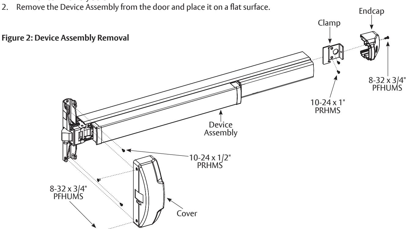
C. Remove Device Assembly
The Device Assembly must first be removed from the door to install the Exit Alarm Kit. Refer to Figure 2 while following the steps to remove the Device Assembly:
-
1. Remove the following hardware (retain for re-installation):
- Cover Screws and Cover
- Device Endcap Screw and Device Endcap
- Clamp Screws and Clamp
- Device Assembly Screws
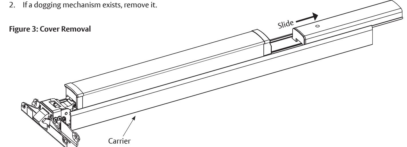
D. Remove Exiting Cover
1. Slide the existing cover off the Carrier, see Figure 3.
Exit Alarm Kit 6116 Series Exit Devices
ASSA ABLOY
Installation Instructions
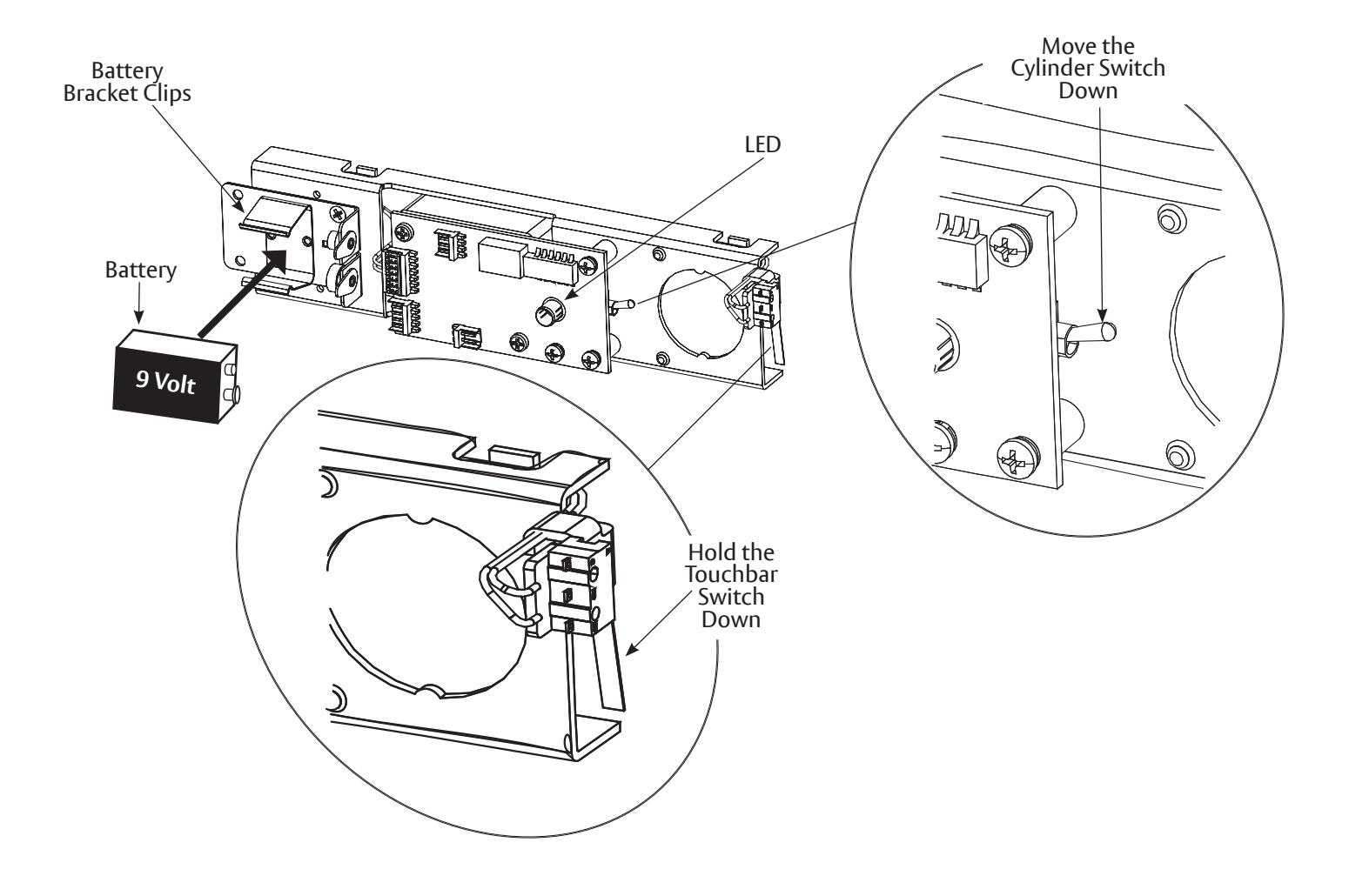
E. Activate and Test the New Alarm Assembly
M Important: Be sure to completely read through this section, in its entirety, prior to proceeding.
1. If necessary for retrofit applications, cut a new Cover Skirt the same size as the old cover. Dispose of the old cover.
Note: The Cover Skirt can be cut to a minimum length of 9-1/4" (235mm).
- 2. Place a 9-Volt battery securely into the Battery Bracket Clips found on the Back of the Alarm Assembly. Push the battery in to engage contacts (Figure 4A).
- 3. Press and hold the lever down on the Touchbar Switch. Move the Cylinder Switch down. The Light-Emitting Diode (LED) will indicate that sensor power is on. A short chirp will indicate that the alarm is activated.
- 4. Release the lever on the Touchbar Switch and the alarm will sound.
- 5. Move the Cylinder Switch back up to the top position to turn off the alarm.
Figure 4A: Activate and Test the New Alarm Assembly
Exit Alarm Kit 6116 Series Exit Devices Installation Instructions
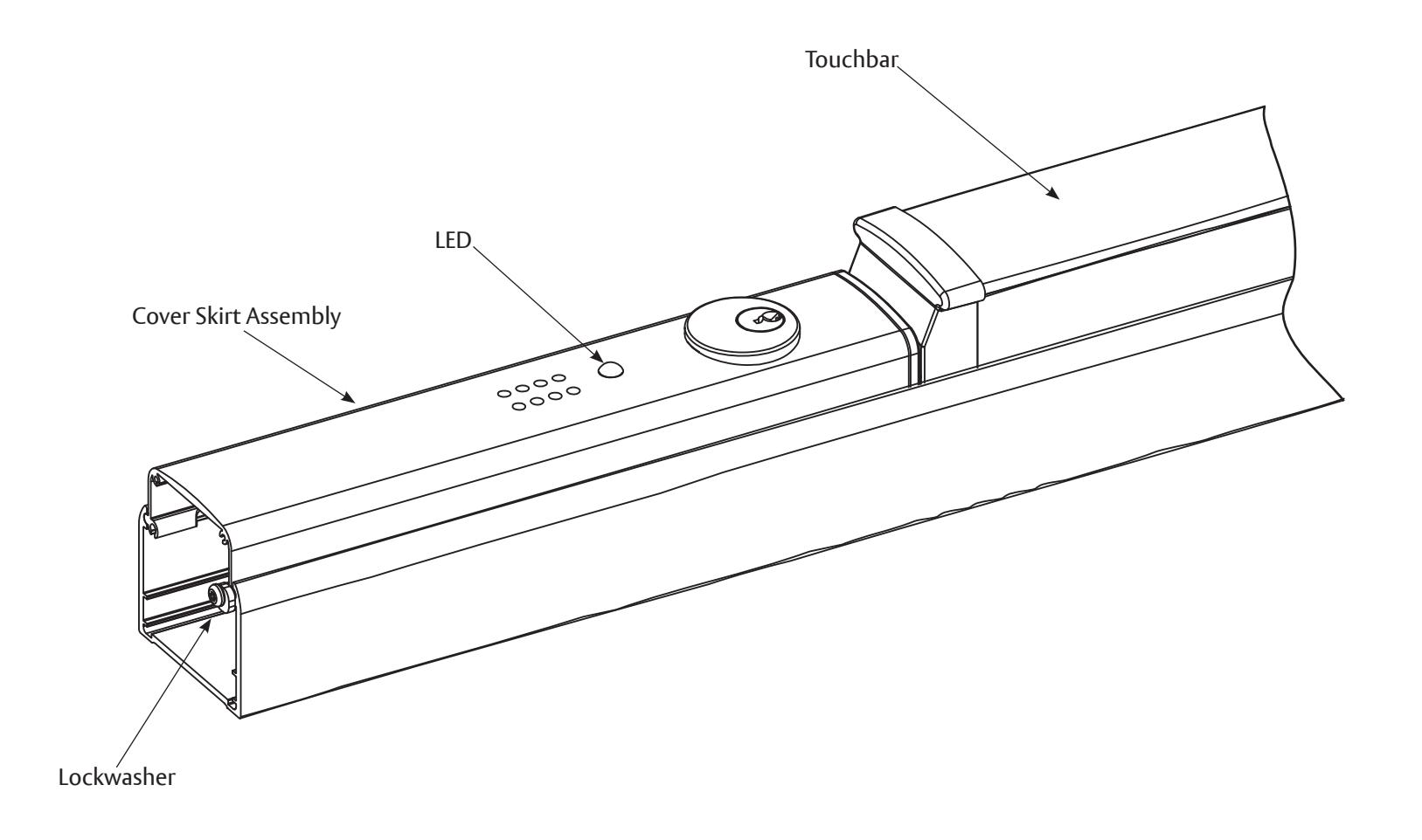
- 6. Push the alarm assembly into the cover skirt assembly (Figure 4B).
- 7. Insert the cylinder, collar (if required) and activator and nut. Tighten nut. Be sure that the activator is sitting properly and can move freely.
- 8. Be sure the LED aligns with the LED opening on the Cover Skirt Assembly.
- 9. Screw the Lock Washer into the Cover Skirt Assembly.
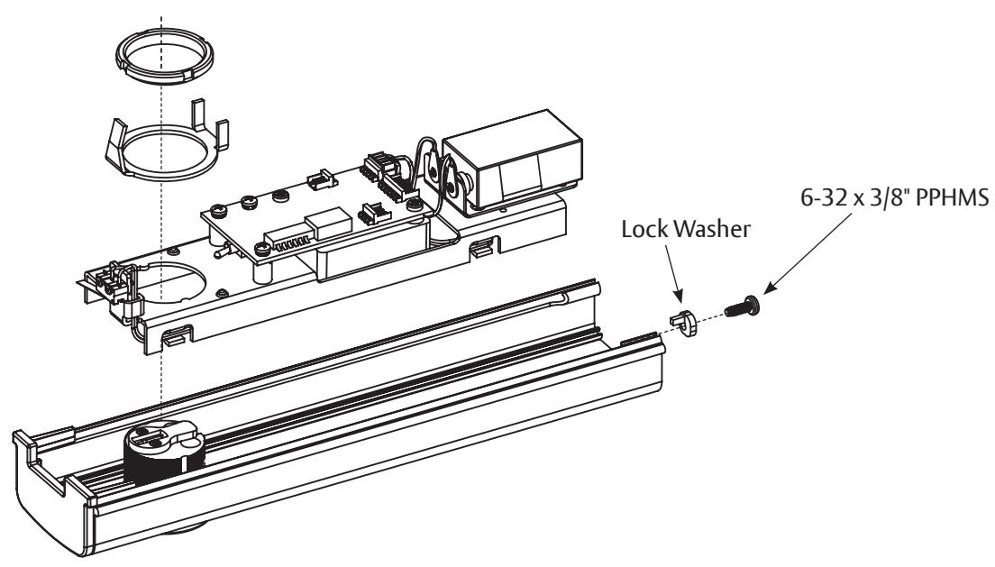
Figure 4B: Alarm Assembly
F. Mounting the Switch Lever
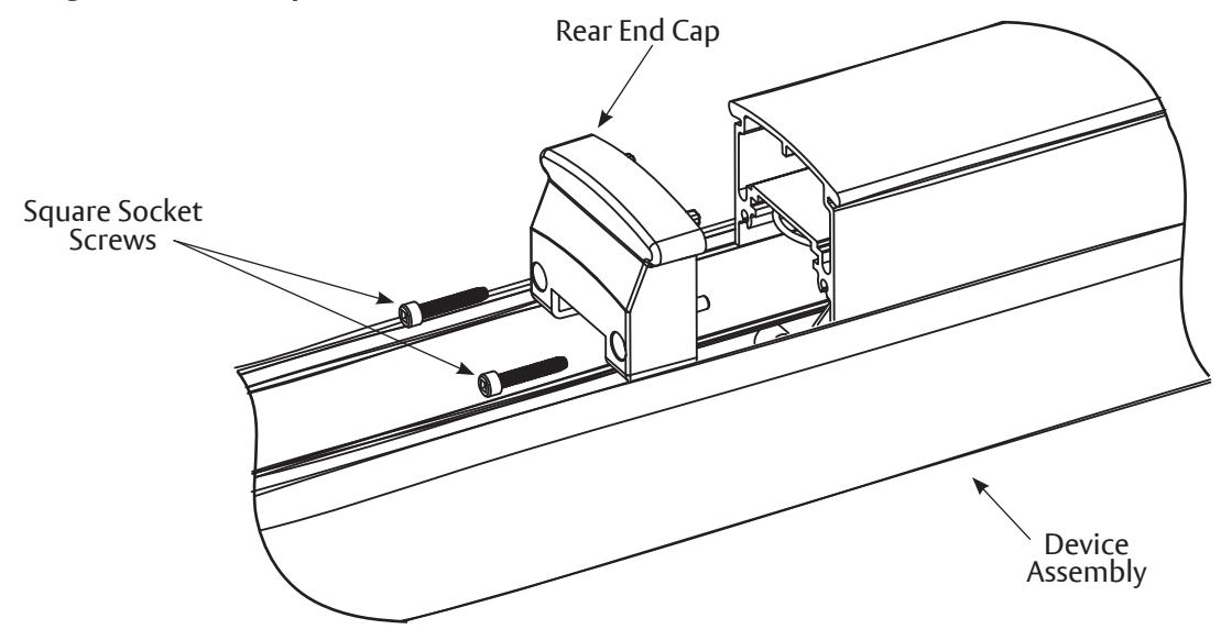
1. Remove the Rear End Cap using a #2 square socket screwdriver (Figure 5A).
Figure 5A : Removing the Rear End Cap
Exit Alarm Kit
6116 Series Exit Devices
Installation Instructions
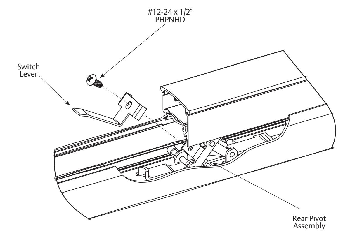
- 2. Screw the Switch Lever onto the Rear Pivot Assembly using a self tapping screw (Figure 5B).
- 3. Screw the Rear End Cap back into the Assembly.
Figure 5B: Switch Lever
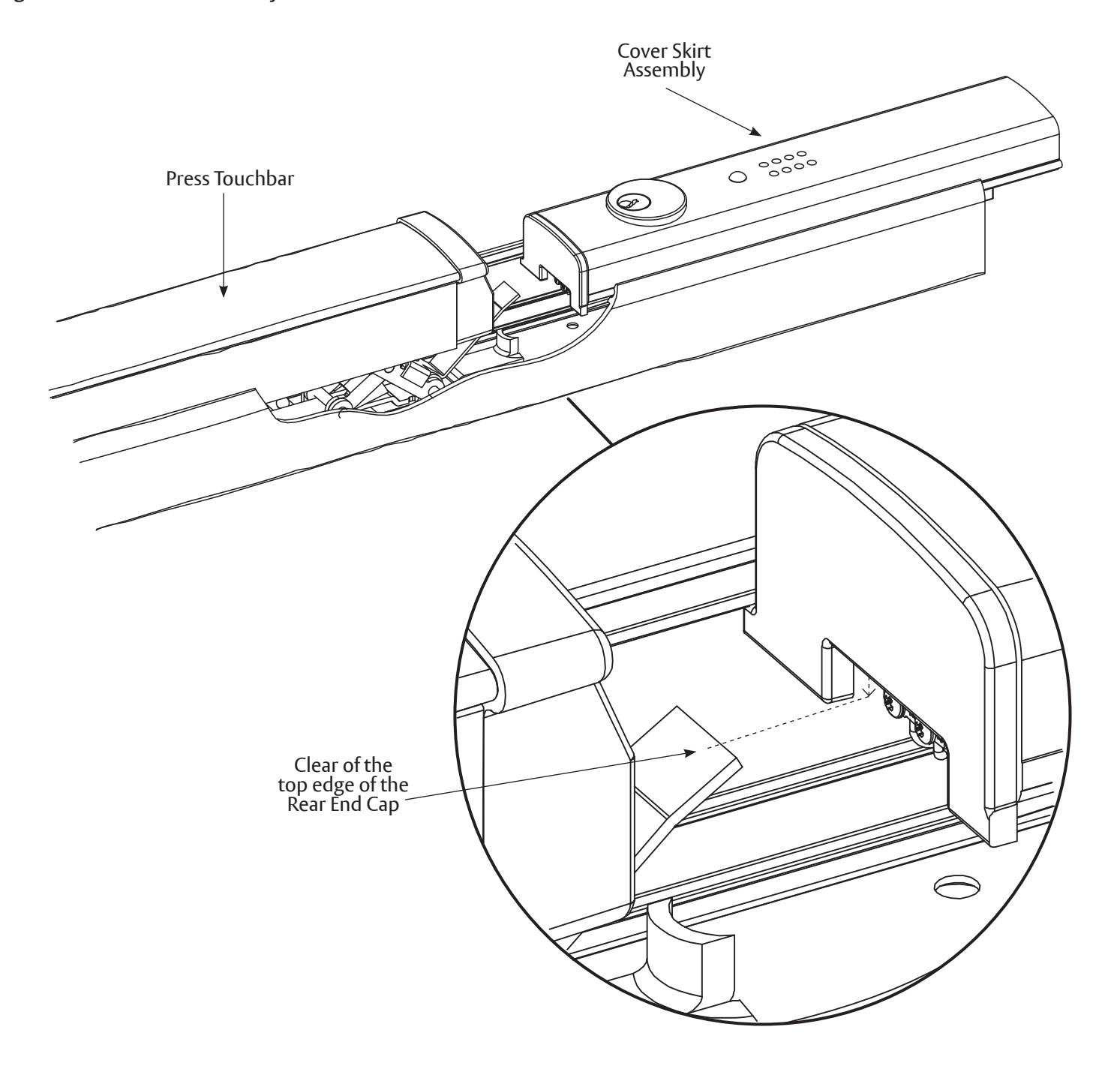
4. Slide the Cover Skirt Assembly while pressing the Touchbar down enough so the Touchbar Switch clears the top edge of the Rear End Cap (Figure 5C).
Figure 5C: Cover Skirt Assembly Placement
Exit Alarm Kit
Installation Instructions
6116 Series Exit Devices
- 5. Push the Alarm Assembly until the Lockwasher prevents further advancement (Figure 5D). When the Touchbar is pressed, the Switch Lever will move up and down enough to make contact with the Alarm Switch.
- 6. Reinstall all device covers and screws.
Figure 5D: Cover Skirt Assembly
Exit Alarm Kit 6116 Series Exit Devices Installation Instructions
G. Exit Bar Installation
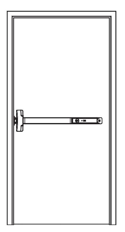
1. Reinstall the Device Assembly on the door (Figure 6A).
Figure 6A: Device Assembly Installed on the Door
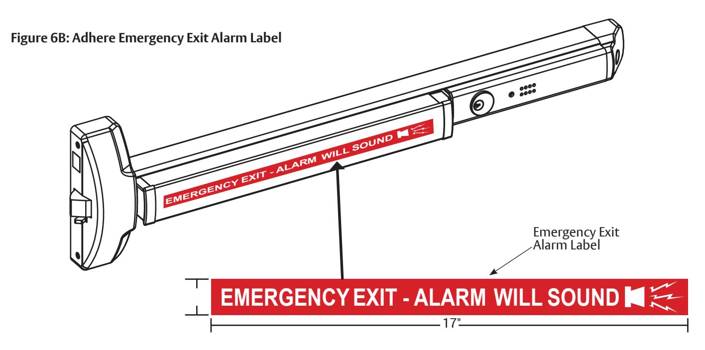
2. Adhere the Emergency Exit Alarm Label onto the flat portion of the Touchbar (Figure 6B).
Exit Alarm Kit 6116 Series Exit Devices
Installation Instructions

H. Testing
-
1. Check the following parts to be sure they are operating properly:
- Trim and Touchbar
- Strike Plate and Bolt Engagement
- Key
-
2. Test the alarm, as follows:
-
a. To actuate the alarm, turn the key clockwise. Wait 20 seconds to hear a confirmation chirp.
- 1. Press the Touchbar to be sure the alarm sounds.
- 2. Turn the key counter-clockwise to shut off the alarm.
-
b. Actuate the alarm again by turning the key clockwise. Wait 20 seconds to hear a confirmation chirp.
- 1. Slide the Alarm Assembly as if removing it. The alarm should sound.
- 2. Turn the key counter-clockwise to shut off the alarm.
-
a. To actuate the alarm, turn the key clockwise. Wait 20 seconds to hear a confirmation chirp.
- 3. Testing is complete if the alarm was activated successfully in numbers 2.a.1. and 2.b.1.
- 4. Refer to Section I if the alarm did not sound during testing.
I. Troubleshooting
If the Alarm will not sound, check the following:
- The Switch Lever may be out of position. The end of the Switch Lever should be touching the Alarm Switch. Turn the Switch Lever Screw until the end contacts the Alarm Switch (Section F).
- The Battery is not connecting. Be sure the battery is placed securely. Press to make contact (Section E).
- The Alarm is not armed.
To actuate the alarm, turn the key clockwise. Wait 20 seconds to hear a confirmation chirp. The Battery needs to be replaced.
If the Alarm chirps every 30 seconds:
• This is a low battery indicator and the battery needs to be replaced.
J. Maintenance
Periodically replace the 9-Volt battery to keep the Alarm Switch Activator working properly.