ASSA ABLOY ACCENTRA 5400LN Series Cylindrical Locks Installation Instructions_80-9150-0056-010
Open the original PDF document
View PDF5400LN Series Grade 1 Cylindrical Lever Lockset
Installation Instructions

Tools Required
- y 2-1/8" (54mm) hole saw
- y 1" (26mm) drill bit
- y 5/16" (8mm) drill bit
- y 7/64" (2.5mm) drill bit
- y Chisel & hammer
- y #2 Phillips screw driver
y Handle removal tool (supplied) 3/8" or 1/2" drill
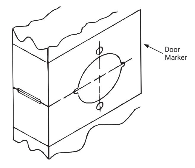
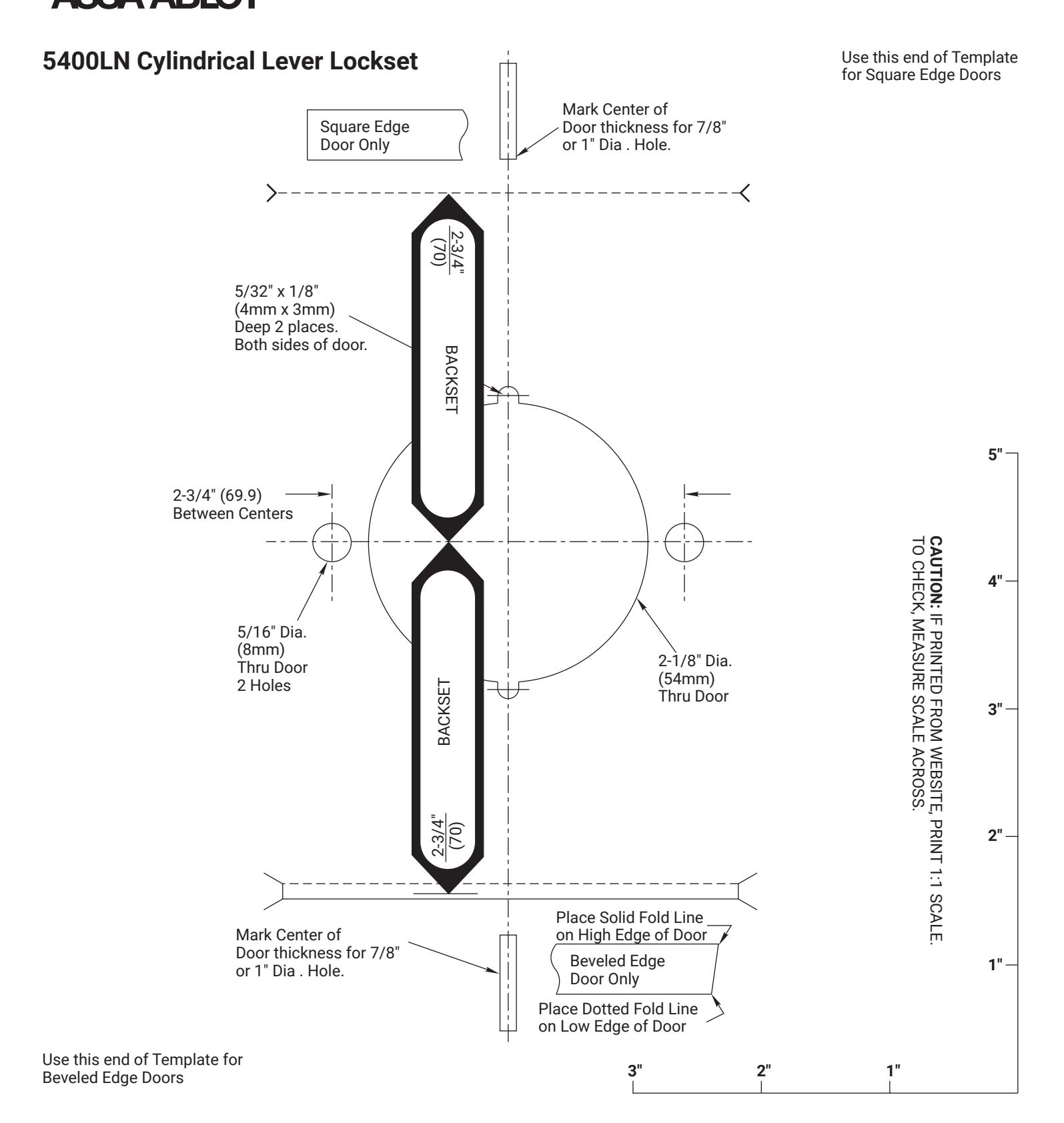
1. Mark Door
Mark horizontal line across edge of door. 40-5/16" (102cm) is the usual height above the floor. Fold template over edge of door, centering on horizontal line. Mark centers of holes at proper backset. For beveled and square edge doors, mark both sides of the door.
NOTE: Be sure to verify backset before marking & drilling door.
Important: The accuracy of the door preparation is critical for the proper functioning and security of this lever handle lock. Misalignment can cause premature wear and tear and a lessening of security.
Attention Installer: Installation of cylindrical locks and latches must be through bolted in all doors. If installation instructions are not followed this may result in damage to the lock and void the factory warranty. Any retrofit or other field modification to a fire rated opening can potentially impact the fire rating of the opening, and ASSA ABLOY ACCENTRA™ makes no representations or warranties concerning what such impact may be in any specific situation. When retrofitting any portion of an existing fire rated opening, or specifying and installing a new fire-rated opening, please consult with a code specialist or local code official (Authority Having Jurisdiction) to ensure compliance with all applicable codes and ratings.
WARNING
This product can expose you to lead which is known to the state of California to cause cancer and birth defects or other reproductive harm. For more information go to www.P65warnings.ca.gov.
WARNING
Attention Installer: Any retrofit or other field modification to a fire rated opening can potentially impact the fire rating of the opening, and ASSA ABLOY makes no representations or warranties concerning what such impact may be in any specific situation. When retrofitting any portion of an existing fire-rated opening, or specifying and installing a new fire-rated opening, please consult with a code specialist or local code official (Authority Having Jurisdiction) to ensure compliance with all applicable codes and ratings.

Cylindrical Lever Lockset Installation Instructions
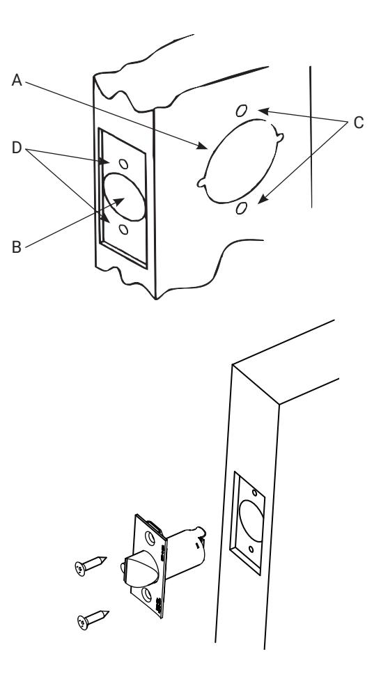
2. Drill door.
- 1. Drill 2-1/8" (54mm) dia. hole (A) thru the door. Cut notches as shown on template. See note. (Except Dummy Trim)
- 2. Drill 1" (26mm) dia. hole (B) in edge of door. Mortise for latch front 1-1/8" (29mm) wide x 2-1/4" (57mm) high x 5/32" (4mm) deep. (Except Dummy Trim) .
- 3. Drill two (2) 5/16" (8mm) dia. holes (C) thru door. See note.
- 4. Drill pilot holes (D) for latch screws. 7/64" (2.5mm) dia. (Except Dummy Trim)
NOTE: To avoid splintering wood doors, drill holes (A) and (C) from both sides of the door.

- 1. Insert latch in door. (Be sure bevel edge of bolt faces strike plate.)
- 2. Attach with two screws supplied.
4. Unpack lock
Cylindrical Lever Lockset Installation Instructions

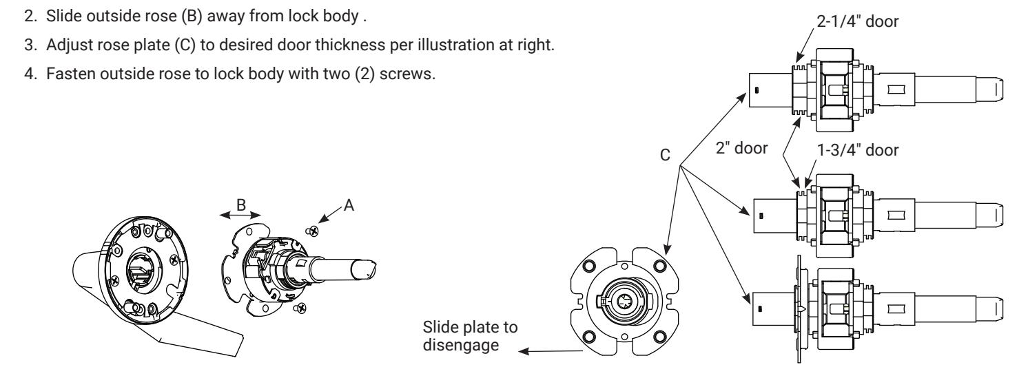
5. Adjust lock for door thickness (if necessary).
(Lock is packed preadjusted for 1-3/4" (44mm) doors. Available for 2-1/4" (57mm) doors upon request.)
To Adjust for Thicker Door
1. Remove two (2) screws (A) from outside rose.
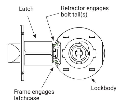
6. Install lock
Insert lockbody into door from outside making sure that lockbody frame hooks latch case and retractor engages bolt tail(s). DO NOT FORCE. (If lockbody does not engage latch easily, check door preparation for errors.)

Cylindrical Lever Lockset Installation Instructions
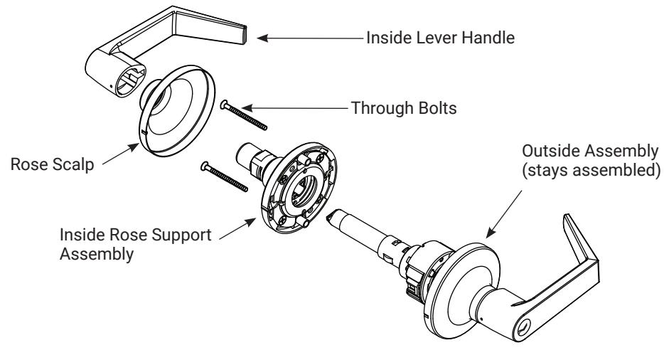
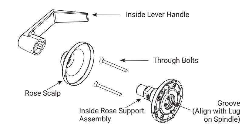
7. Install inside components
-
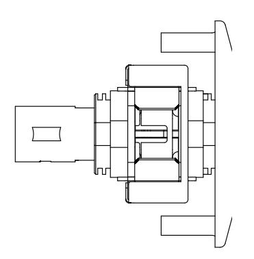
1. Slide inside rose assembly onto lock body.
- NOTE: The groove (see right) must line up with drive lug on spindle. Fasten rose assembly with two thru bolts.
- 2. Place rose scalp on rose assembly.
- 3. Install lever handle. Snap in place, pull to insure properly seated. (See Next Page For Double Cylinder)
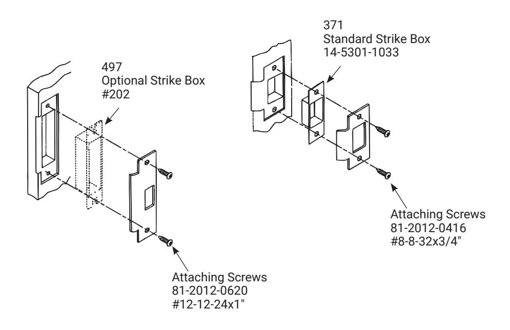
8. Strike installation (Wood Frames Only)
- 1. Close door and mark a horizontal line from the center of the template to the frame of the door.
- 2. Measure half the thickness of the door. Mark this same distance with a vertical line starting from the stop side of the frame and where both lines cross. Make a 1 inch (26mm) diameter hole and 1/2 inch (13mm) in depth.
- 3. Align the holes of the strike with the vertical line. Trace the outline of the strike and mortise with 1/16 inch (1.6mm) depth. Attach the strike with two screws (provided).
TEST THE OPERATION OF THE LOCKSET: Cycle the lock in both the locked and unlocked positions. If lock functions smoothly when door is open, but binds when closed, check door and frame alignment. If problems are found see Troubleshooting on page 5.
Cylindrical Lever Lockset Installation Instructions

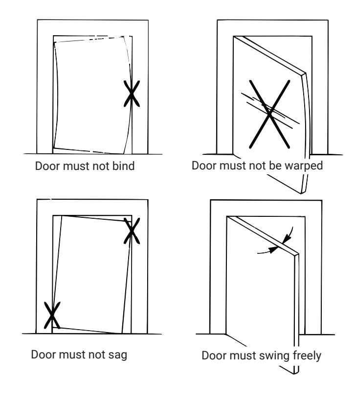
Troubleshooting
- 1. Check door for proper installation (see pictures below). Verify 1/8" between the latch and strike.
- 2. Check hinges. They should not be loose or have excessive wear on knuckles.
- 3. If Latchbolt will not deadlock: Either strike is out of line or gap between door and jamb is too great. Realign strike or shim strike out towards flat area of latchbolt.
-
4. If Latchbolt does not retract or extend properly: Latchbolt tail and retractor may not be properly positioned.
- a. Remove lockset. Look through 2-1/8" hole and verify latchbolt tail is centered between top and bottom of hole.
- b. Remove latchbolt and insert lockset. Look through latch hole and verify retractor mouth is centered in hole. Adjust outside rose plate if not. (See #5 on page 3)
- c. Rebore holes if necessary to line up retractor and tail.

Cylindrical Lever Lockset Installation Instructions
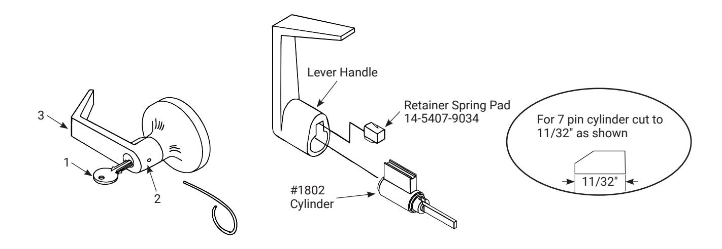
To remove cylinder handle
- 1. Insert key and rotate clockwise 70°.
- 2. Depress retainer with tool provided.
- 3. Slide lever off lock. (Also applies to inside lever of 5417N, 5421LN and 5430LN lock functions.)
To remove cylinder from handle
- 4. Remove retainer spring pad.
- 5. Slide cylinder out of handle.
To reassemble reverse procedure. (Be sure spacer is installed on back of cylinder plug.) Water may be used to lubricate spring pad to aid installation.
Cylindrical Lever Lockset Installation Instructions

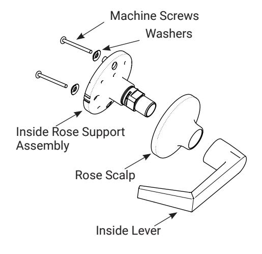
Dummy trim installation
Secure the Rose Support assembly to the door using screws and washers provided and install the rose scalp and inside lever.
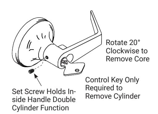
To remove inside handle of 5417LN and 5418LN functions (removable core cylinder)
- 1. Remove set screw.
- 2. Slide handle off. Do not over tighten set screw when assembling.
5428LN, 5429LN and 5439LN Functions Only Adjust for Door Thickness
Finish care
This lockset is designed to provide the highest standard of product quality and performance. Care should be taken to ensure a long-lasting finish. When cleaning is required use a soft,damp cloth. Using lacquer thinners, caustic soaps, abrasive cleaners or polishes could damage the coating and result in tarnishing.

Cylindrical Lever Lockset Installation Instructions
Cylindrical Lever Lockset Installation Instructions


Cylindrical Lever Lockset Installation Instructions
Cylindrical Lever Lockset Installation Instructions