ASSA ABLOY ACCENTRA 5400 Series Cylindrical Locks Installation Instructions_80-9150-0003-010
Open the original PDF document
View PDF5400 Series Grade 1
Cylindrical Knob Lockset
Installation Instructions
Mark line across edge of door for
centerline of lock. Fold template over edge of door, centering on horizontal
line. Mark centers of holes at proper
1. Mark Door
backset.
ASSA ABLOY
Tools Required
- Chisel & hammer 2 1/8" (54mm) hole saw
- #2 phillips screw driver 1" (26mm) boring bit
- Handle removal tool (supplied) 7/64" (2.8mm) drill bit 3/8" or I/2" drill
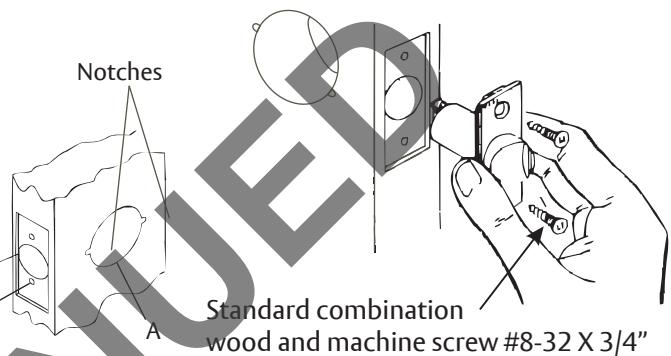
2. Drill Door
- A. Drill 2-1/8" (54mm) hole thru the door. Cut Notches as shown on the template.
- B. Drill 1" (25mm) hole in edge of door. Cut out for latch front 1-1/8" (29mm) wide X 2-1/4" (57mm) high X 5/32" (4mm) deep.
- C. Drill (2) 7/64" (2.8mm) holes for latch assembly
3. Install Latch Unit
Install latch assembly with screws provided.
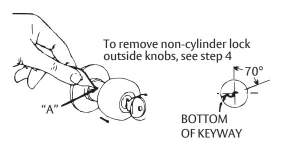
4. Remove Inside Knob
To remove knob, depress retainer with small end of spanner wrench, through small hole "A" in trim cap. Keep spanner wrench perpendicular with spindle. Pull knob off. Remove inside rose by unscrewing counterclockwise. For cylinder knob see step 8 and 9
inside rose by unscrewing counterclockwise. For cylinder knob see step 8 and 9.
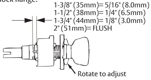
5. Adjust for Door Thickness If necessary
(Lock is packed preadjusted for 1-3/4" (44mm) doors.
Rotate the outside rose nut assembly until proper dimension is reached for required door thickness. Measure from the end of the pin to the lock flange.
6. Install Lock
With lock case in place, insert lock assembly into 2-1/8" (54mm) hole, making sure that lock case hooks the retainer legs and retractor engages the bolt tail.
Caution: Do Not Force
If Lockbody does not engage latch easily, check door prep for errors.
LOCK CASE RETAINER LEG BOLT TAIL RETRACTOR LATCH CASE
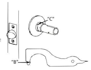
7. Attach Inside Rose
Slide inside rose over inside spindle and sleeve and screw rose into place. Tighten securely with spanner wrench supplied. Catch small lug "B" of spanner wrench in small hole "C" in rose and turn clockwise until tight.
⚠ WARNING
This product can expose you to lead which is known to the state of California to cause cancer and birth defects or other reproductive harm. For more information go to www.P65warnings.ca.gov.
MARNING
Attention Installer: Any retrofit or other field modification to a fire rated opening can potentially impact the fire rating of the opening, and ASSA ABLOY makes no representations or warranties concerning what such impact may be in any specific situation. When retrofitting any portion of an existing fire-rated opening, or specifying and installing a new fire-rated opening, please consult with a code specialist or local code official (Authority Having Jurisdiction) to ensure compliance with all applicable codes and ratings.
80-9150-0003-010 03/24
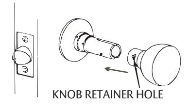
8. Install Inside Knob
Slide knob onto spindle. With knob retainer hole in knob facing edge of door push until retainer snaps into place.
9. Removal/Installation of Outside Knob Assembly
To remove the outside knob assembly rotate the key to 70° clockwise. Depress retainer through small hole "A". Slide knob assembly off spindle.
To install the outside knob assembly remove the key. Align knob with the spindle so that the keyway is facing down. Slide the knob onto the spindle until the bottom of the knob assembly rests on the retainer. Insert the key and rotate it 70° and slide the knob over the retainer. Pull on the knob to assure proper seating of the knob assembly.
- Note 1: Locksets are setup for right hand doors. If left handing is required remove the knob assembly and rotate the knob assembly 180° and use the above instructions for reassembly.
- Note 2: When Installing the -08 function knob assembly it will be necessary to rotate the plug bar until the lockbody is in the locked position. Continue with above installation instructions.
10. Interchangable Core Cylinders
Install cylinder into Knob. Slide knob assembly onto spindle so that the slot on the driver aligns with the bar in the spindle. Insert operation key and rotate 70° clockwise, then push knob into position.

TEST THE OPERATION OF THE LOCKSET
Cycle the lock in both the locked and unlocked positions. If lock functions smoothly when door is open, but binds when closed, check door and frame alignment. If problems are found see troubleshooting below.
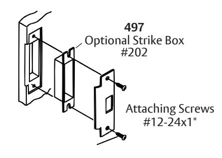
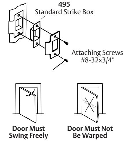
11. Strike Installation (Wood Frames Only)
- A. Close door and mark a horizontal line from the center of the template to the frame of the door.
- B. Measure half the thickness of the door; mark this same distance with a vertical line starting from the stop side of the frame and where both lines cross make a 1" (26mm) diameter hole and 1/2" (13mm) in depth.
- C. Align the holes of the strike with the vertical line, trace the outline of the strike and mortise to 1/16" (1.6mm) depth. Attach the strike with two screws (provided).
Troubleshooting
- 1. Check door.
- 2. Check hinges. They should not be loose or have excessive wear on knuckles.
- 3. Latchbolt will not deadlock.
Either strike is out of line or gap between door and jamb is too great. Realign strike or shim strike out towards flat area of latchbolt.
4. Latchbolt does not retract or extend properly.
Latchbolt tail and retractor not properly positioned.
- A. Remove lockset. Look through 2 1/8 hole and verify latchbolt tail centered between top and bottom of hole.
- B. Remove latchbolt and insert lockset, look through latch hole and verify retractor mouth centered in hole. Adjust outside rose plate if not. (See #5)
- C. Rebore holes if necessary to line up retractor and tail.
Door Must Not Sag
80-9150-0003-010 03/24
Door Must Not Bind