ASSA ABLOY ACCENTRA 533F Series Trim (Discontinued) Installation Instructions_80-8470-0533-000
Open the original PDF document
View PDF1. Assemble trim. See other side for components and instructions.
Installation Instructions
REFERENCE (& Trim)
VERTICAL
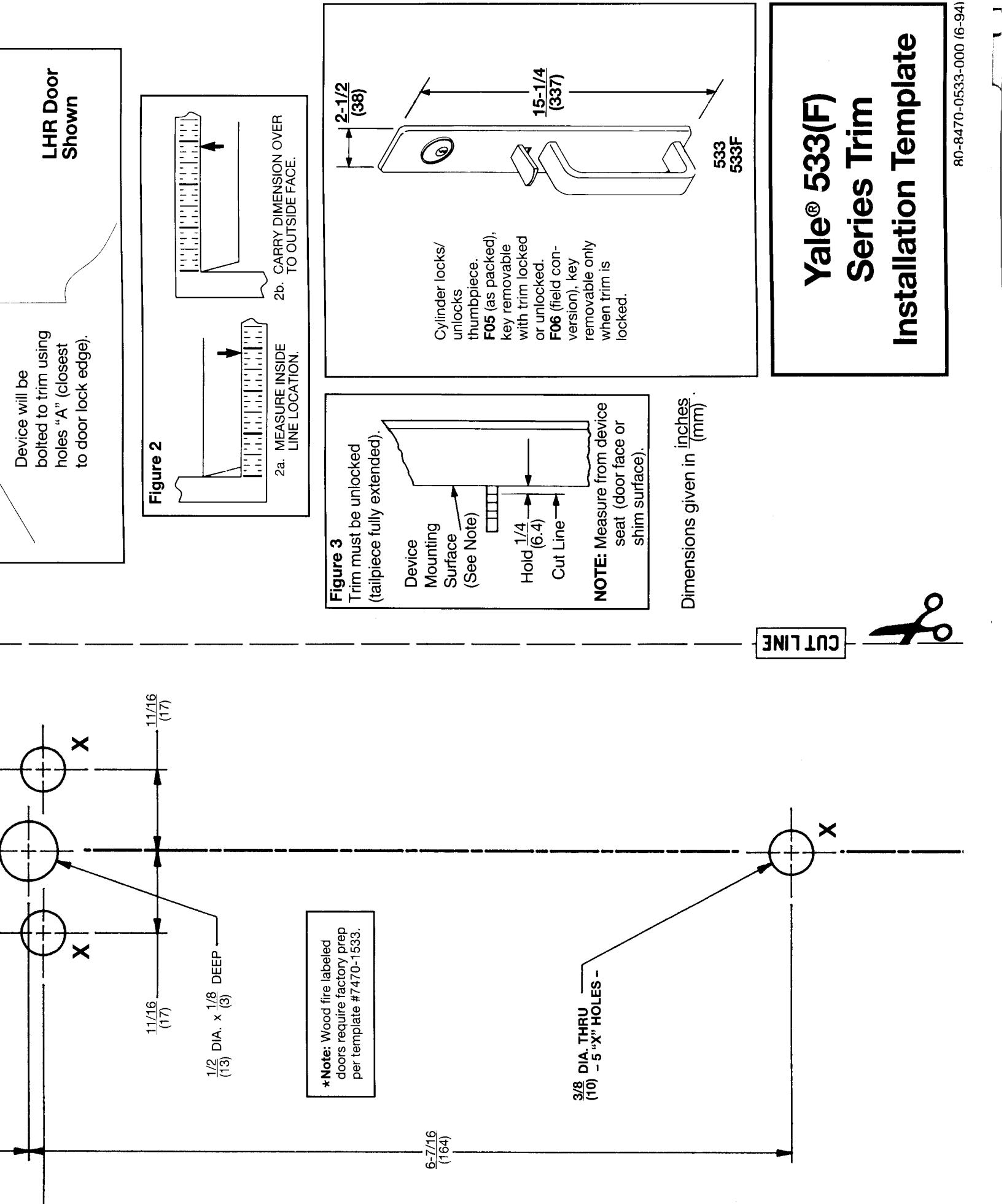
- After marking door inside face for Follow steps 2a. and 2b., in Figure device location (Device Instruc-2 below. Centerline" from inside door face. tions), carry "Vertical Reference
pull bottom stud.
Ņ
- 3. Carry "Horizontal Reference Centerline" from inside to outside
- Align trim template and tape to original template packed with the trim, use only the dimensions written on the use as a door marker. If this is not the machines may change the size of a draw- CAUTION: Office copiers and facsimile door outside face. door face ing and make the template inaccurate to
ထု
template to locate the holes on the door
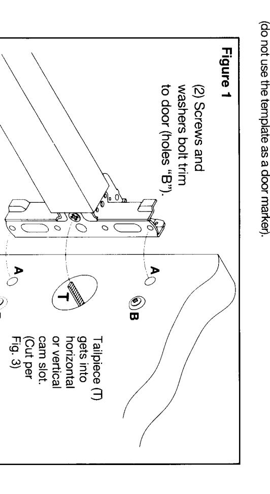
- ტ 5. Spot holes and prepare door for trim. Mount trim to door. Fasten finger in Figure 1, plus one engaged to washers seating on door, as shown tight only with 2 screws and
- With trim unlocked (tailpiece depressed) cut trim tailpiece as shown in Figure 3. turning when thumbpiece is
- Seat device so that trim tailpiece device instructions penetrates cam slot, as shown in Figure 1. Continue as shown in
533(F) Trim Assembly Instructions
- 1. Check cylinder components. See "Cylinder Applications" chart. Non-standard cylinder rings and mounting screws must be supplied with optional cylinders.
- 2. Assemble cylinder. Insert Cylinder Housing prongs into Escutcheon matching notches. Pass Cylinder tail-piece thru Cylinder Ring and Cylinder Housing slot in cam. Bolt Cylinder seated in Cylinder Ring recess (DO NOT OVERTIGHTEN SCREWS).
- Check cylinder action. Cylinder must freely rotate tailpiece into lock (cam pushing locking lever down) and unlock (shown) positions. When lock-
- ing lever is engaged, it depresses the Trim spindle. The thumbpiece handle is, thus, disengaged from the spindle.
- 4. Cut cylinder tailpiece. Correct length is 1/16" to 3/16" (2 to 5mm) beyond Cylinder Housing cam.
- Determine trim function. F05: As shipped. Key locks/unlocks thumbpiece handle.
Key removable in lock and
unlock positions. F06: Field move Function Screw to hole in Cylinder Housing under cam tip. Key locks/unlocks thumbpiece handle. Key removable ONLY
in lock position.
Rim Cylinder
(May be supplied by others.) Standard: 1109 6-Pin, with 2 keys.
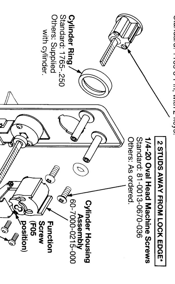
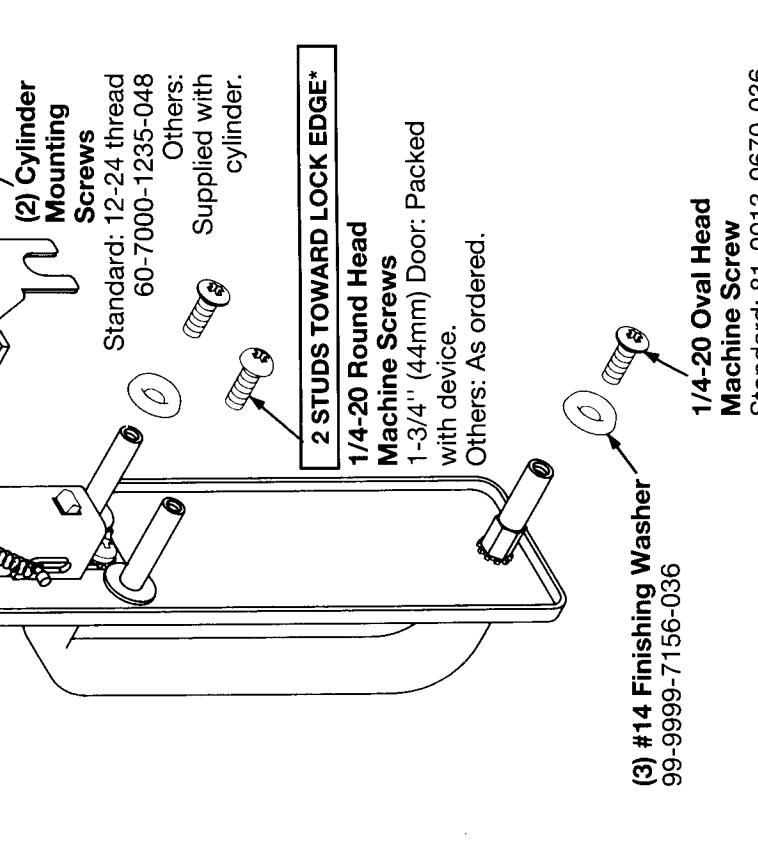
Machine Screw Standard: 81-0013-0670-036 Others: As ordered.
*Shown for LHR door.
| EWS | · . | ||||||||||||
|---|---|---|---|---|---|---|---|---|---|---|---|---|---|
| CYLINDER APPLICATIONS | Cylinder Ring | Cylinder Ring "L" = (Cylinder "A"-1") | Cylinder Ring "L" = (Cylinder "A"-25mm) | CYLINDER MOUNTING SCREWS | 60-7000-1235-048 (STD.) | 34-2311-8738-048 | 10-1193-1018-048 | 60-7000-1235-048 | |||||
|
(
|
(38) | - - - | | CYLINDER RING | 1765250 (STD.) | 1765406 | 1765656 | 1765750 | 1765437 | 1765656 | 1766 | |||
| Rim Cylinder | A | YALE CYLINDER | 6-PIN, 1109 (STD.), 5109 | 7-PIN, 1109, 5109 | 6-PIN, 1709 (CMK) | 7-PIN, 1709 (CMK) | 6-PIN, 1193 (RC) | 7-PIN, 1193 (RC) | 6-PIN, U5109 (HS) | 7-PIN, U5109 (HS) | |||
80-8470-0533-000 (6-94)