ASSA ABLOY ACCENTRA 522F & 526F Series Trim (Discontinued) Installation Instructions_80-8470-0522-000
Open the original PDF document
View PDF
Installation Instruction
- 1. Assemble trim. See other side for componer and instructions.
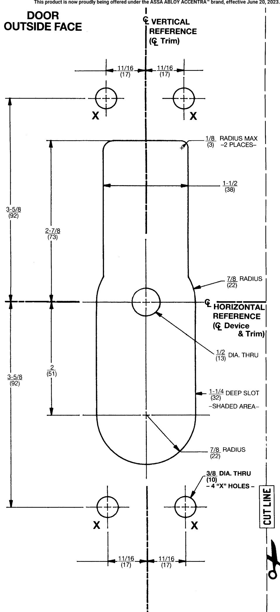
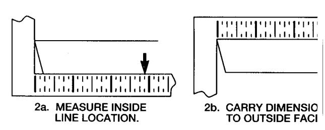
- 2. After marking door inside face for device local (Device Instructions), carry "Vertical Reference Centerline" from inside door face. Follow step 2a, and 2b, below
- 3. Carry "Horizontal Reference Centerline" from inside to outside door face.
- 4. Align trim template and tape to door outside face.
CAUTION: Office copiers and facsimile machines ma change the size of a drawing and make the template inaccurate to use as a door marker. If this is not the original template packed with the trim, use only the dimensions written on the template to locate the hole: on the door (do not use the template as a door marke
- 5. Spot holes and prepare door for trim.
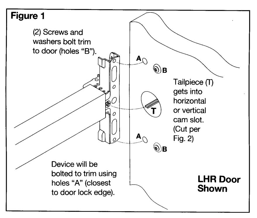
- Mount trim to door. Fasten finger tight only \( \) 2 screws and washers seating on door, as s in Figure 1.
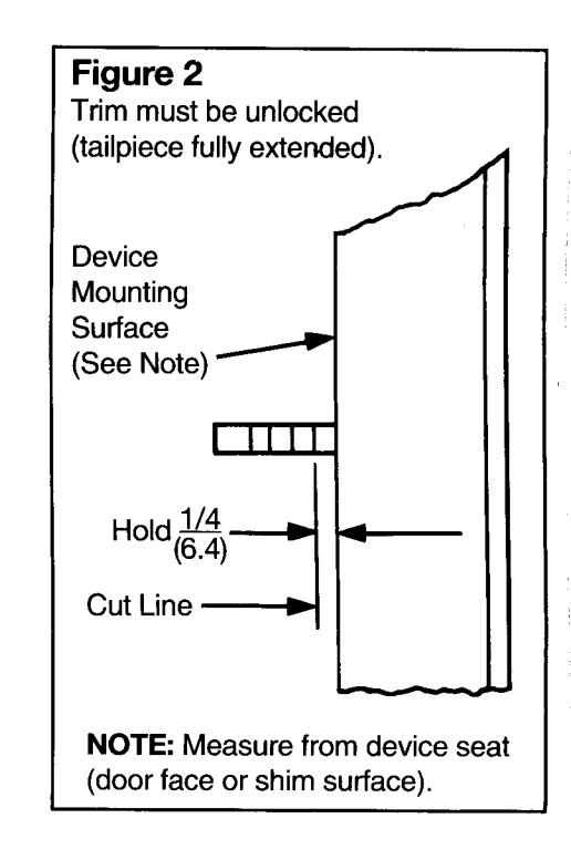
- 7. With trim unlocked (tailpiece turning when le is depressed), cut trim tailpiece as shown in Figure 2.
- Seat device so that trim tailpiece penetrates slot, as shown in Figure 1. Continue as show in device instructions.
tion
OVER
ith
er
am
own
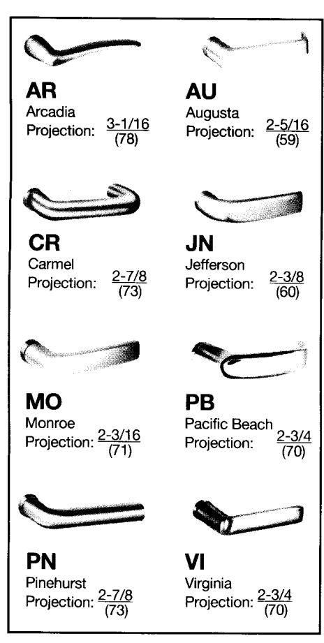
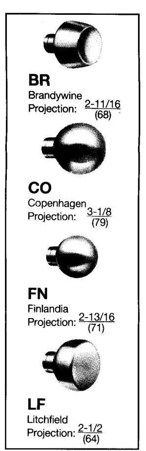
Dimensions given in inches (mm)
Yale® 522(F) & 526(F) Series Trim Installation Template
Note: 526(F) illustrated. 522(F) identical, except that actuator is a knob and trim is non-handed.
| Dim Culindor | Coding down Discou | T | 1 | |
|---|---|---|---|---|
| Rim Cylinder | Cylinder Ring | YALE CYLINDER | CYLINDER RING | CYLINDER MOUNTING SCREWS |
| A |
5/32
(4) |
6-PIN, 1109 (STD.), 5109 | 1765250 (STD.) | - 60-7000-1235-048 (STD.) |
| 7-PIN, 1109, 5109 | 1765406 | |||
|
1-1/2
(38) |
6-PIN, 1709 (CMK) | 1765656 | - 34-2311-8738-048 | |
| 7-PIN, 1709 (CMK) | 1765750 | |||
| 6-PIN, 1193 (RC) | 1765437 | 10-1193-1018-048 | ||
| 7-PIN, 1193 (RC) | 1765656 | |||
| Cylinder Ring "L" = ( | linder "A" 1'') | 6-PIN, U5109 (HS) | 1766 | 60-7000-1235-048 |
| Cylinder "A" – 25mm) | 7-PIN, U5109 (HS) |
522(F) & 526(F) Trim Assembly Instructions
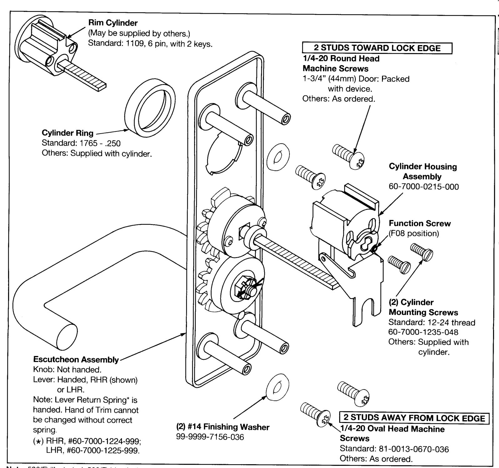
- Check cylinder components. See "Cylinder Applications" chart. Non-standard cylinder rings and mounting screws supplied with cylinders.
- 2. Assemble cylinder. Insert Cylinder Housing prongs into Escutcheon matching notches. Pass Cylinder tailpiece thru Cylinder Ring and Cylinder Housing slot in cam. Bolt Cylinder seated in Cylinder Ring recess (DO NOT OVERTIGHTEN SCREWS).
- 3. Check cylinder action. Cylinder must freely rotate tailpiece into lock (cam pushing locking lever down) and unlock (shown) positions. When locking lever is engaged, it depresses the trim spindle. The knob/ lever handle is, thus, disengaged.
- 4. Cut cylinder tailpiece. Correct length is 1/16" to 3/16" (2 to 5mm) beyond Cylinder Housing cam.
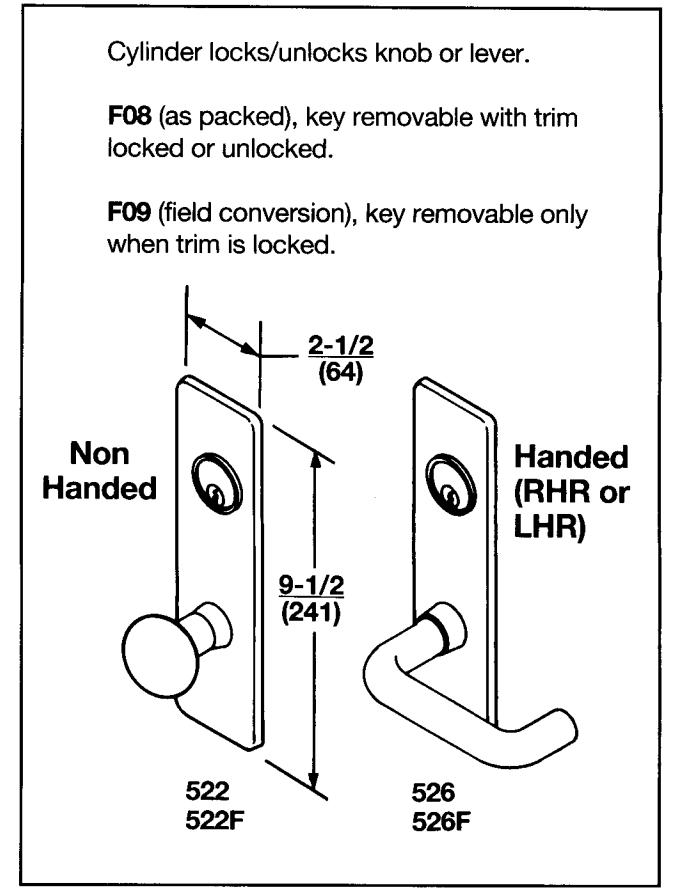
- 5. Determine trim function.
F08: As shipped
Key locks/unlocks knob/lever handle.
Key removable in lock and unlock positions.
F09: Field move Function Screw, to hole in Cylinder Housing under cam tip.
Key locks/unlocks knob/lever handle.
Key removable ONLY in lock position.