ASSA ABLOY ACCENTRA 513F, 517F, 518F & 519F Trims Installation Instructions_80-8470-0513-000
Open the original PDF document
View PDF513F, 517F, 518F & 519F
Trim
Installation Instructions
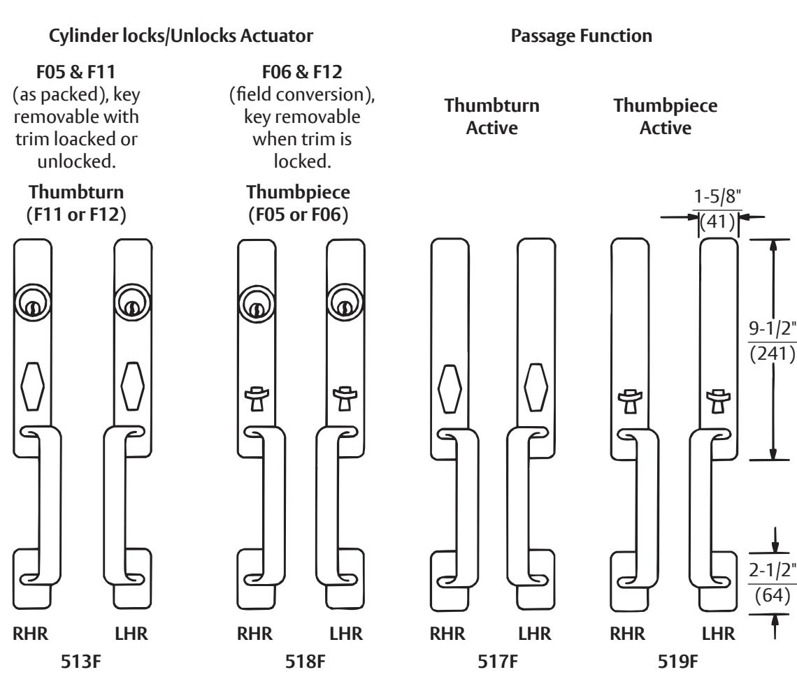
513F, 517F, 518F & 519F Trim
Assembly Instructions
-
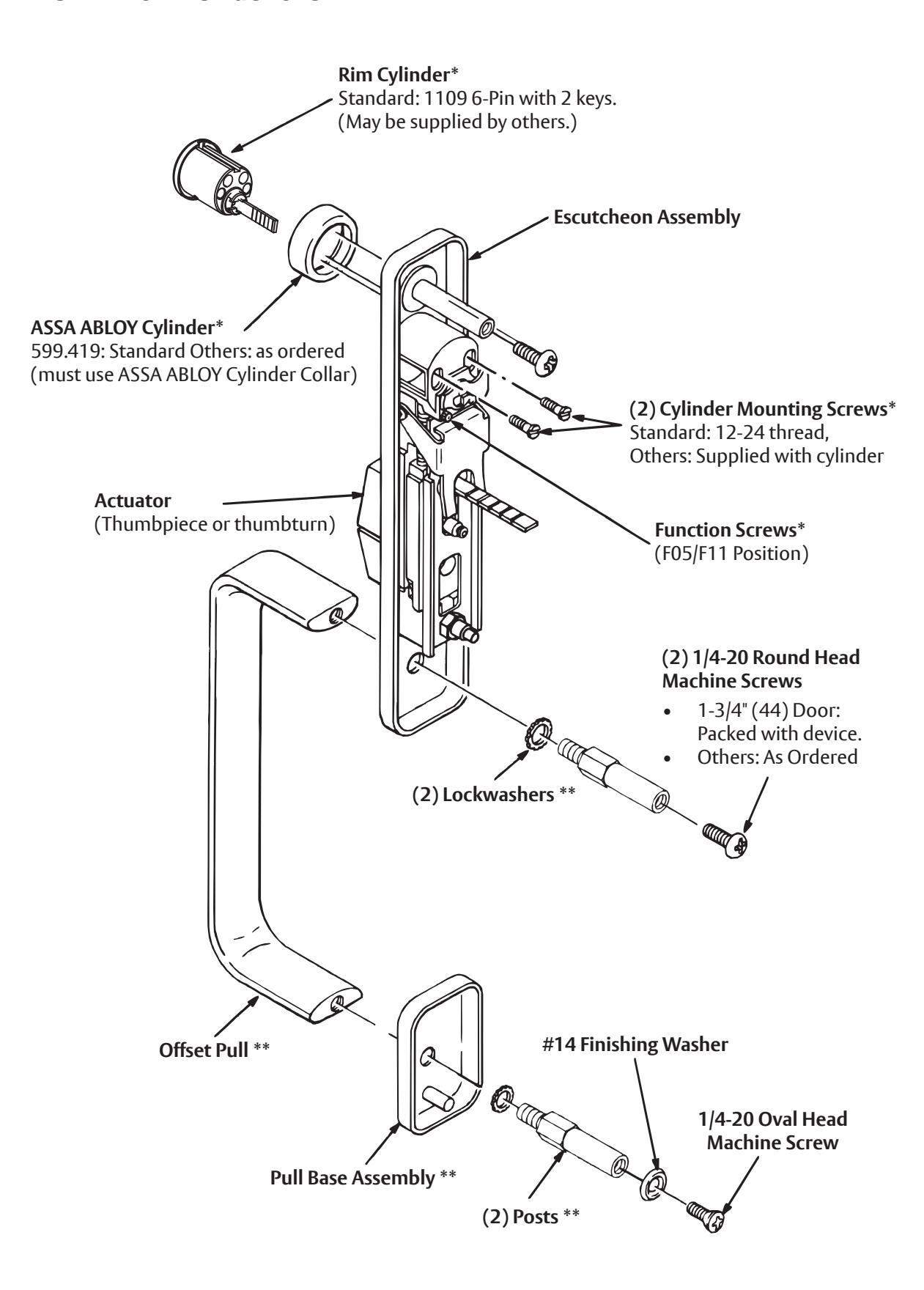
1. 513F & 518F Trim only
- a. Check cylinder components. See Chart. Non-standard cylinder collars should be identified on product order. Non-standard cylinder mounting screws are supplied with cylinders.
- b. Assemble cylinder, use components marked (*). Pass Cylinder tailpiece thru ASSA ABLOY Cylinder Collar and Cylinder Housing slot in cam. Bolt Cylinder seated in Cylinder Collar recess (DO NOT OVERTIGHTEN SCREWS).
- c. Check cylinder action. Cylinder must freely rotate tailpiece into lock (cam pushing locking lever down) and unlock (shown) positions. When locking lever is engaged, it depresses the trim spindle. The thumbturn/thumbpiece is thus disengaged from the spindle.
- d. Cut Cylinder tailpiece (Not Trim tailpiece). Correct length is 1/16 " to 3/16" (2 to 5mm) beyond Cylinder Housing cam.
- e. Determine trim function. F05 & F11: As shipped. Key locks/unlocks thumbturn/thumbpiece. F06 & F12: Field move Function Screw to Cylinder Housing hole under cam tip. Key locks/unlocks thumbturn/ thumbpiece. Key removable ONLY in locked position.
- 2. Assemble pull, offset away from lockedge of door. Use components marked (**).
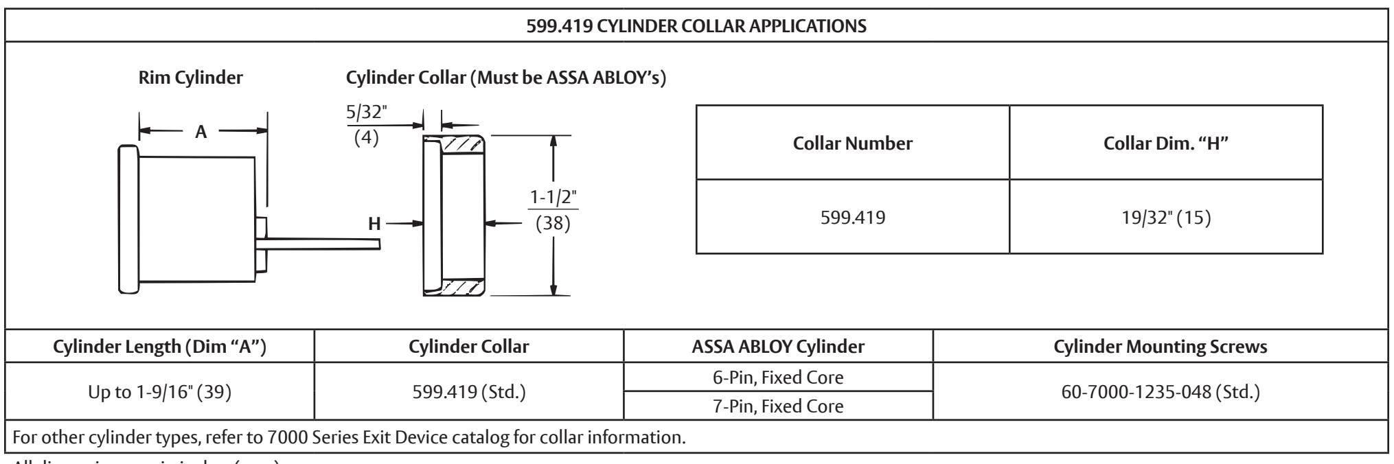
All dimensions are in inches (mm).

This product can expose you to lead which is known to the state of California to cause cancer and birth defects or other reproductive harm. For more information go to www. P65warnings.ca.gov.
WARNING
Attention Installer: Any retrofit or other field modification to a fire rated opening can potentially impact the fire rating of the opening, and ASSA ABLOY makes no representations or warranties concerning what such impact may be in any specific situation. When retrofitting any portion of an existing fire-rated opening, or specifying and installing a new firerated opening, please consult with a code specialist or local code official (Authority Having Jurisdiction) to ensure compliance with all applicable codes and ratings.
80-8470-0513-000 03/24
Installation Instructions
Cut Out Shaded Area 1-3/8" (35) Deep
CL Device
3-3/8" (86)
3/4" (19) Dia. Thru Door
1-1/4" (32)
3-5/8" (92)
3-5/8" (92)
6-7/16" (164)
7/8" (22)
6-3/8" (162)
Device Mounting Holes & Trim
CL
3/8" (10) Dia. Thru – 2 Holes –
CUT LINE
3/8" (10) Dia. x 3/4" (19) Deep
- 1. Pull trim becomes handed after assembly (parts are universal). See other side for components and instructions.
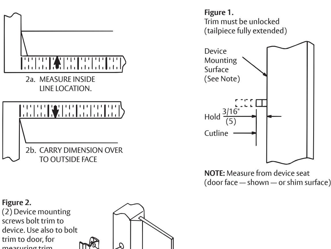
- 2. After marking door inside face for device location (Device Instructions), carry "Centerline of Device Mounting Holes" from outside doorface. Follow steps 2a and 2b, below.
- 3. Carry horizontal "Centerline of Device" from inside to outside door face.
- 4. Align trim template and tape to door, outside face. Caution: Office copiers and facsimile machines may change the size of a drawing and make the template inaccurate to use as a door marker. If this is not the original template packed with the trim, use only the dimensions written on the template to locate the holes on the door (do not use the template as a door marker).
- 5. Spot holes and prepared door for trim.
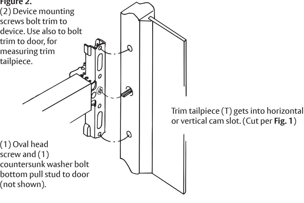
- 6. Mount trim to door. Fasten finger tight with 2 screws (packed with device). see Figure 2 .
- 7. With trim unlocked (tailpiece turning when the thumbturn is rotated or the thumbpiece is depressed), cut trim tailpiece as shown in Figure 1 .
- 8. Seat device so that trim tailpiece penetrates cam slot, as shown in Figure 2 . Continue as shown in device instructions. Bottom pull post fastens to door, with oval head screw seated on countersunk washer (packed with trim).

or in part without the express written permission of ASSA ABLOY Access and Egress Hardware Group, Inc. is prohibited.