ASSA ABLOY ACCENTRA 5110 Series, Hold Open Installation Instructions_80-9351-0105-010
Open the original PDF document
View PDFYale
Hold Open Door Closers Installation Instructions
80-9351-0105-010 (11-08)
An incorrectly installed or improperly adjusted door closer can cause property damage or personal injury. These instructions should be followed to avoid the possibility of misapplication or misadjustment.
Models 5111 5112
5113 5114
With or without prefix "TJ" with or without suffix "BC" or "COV"
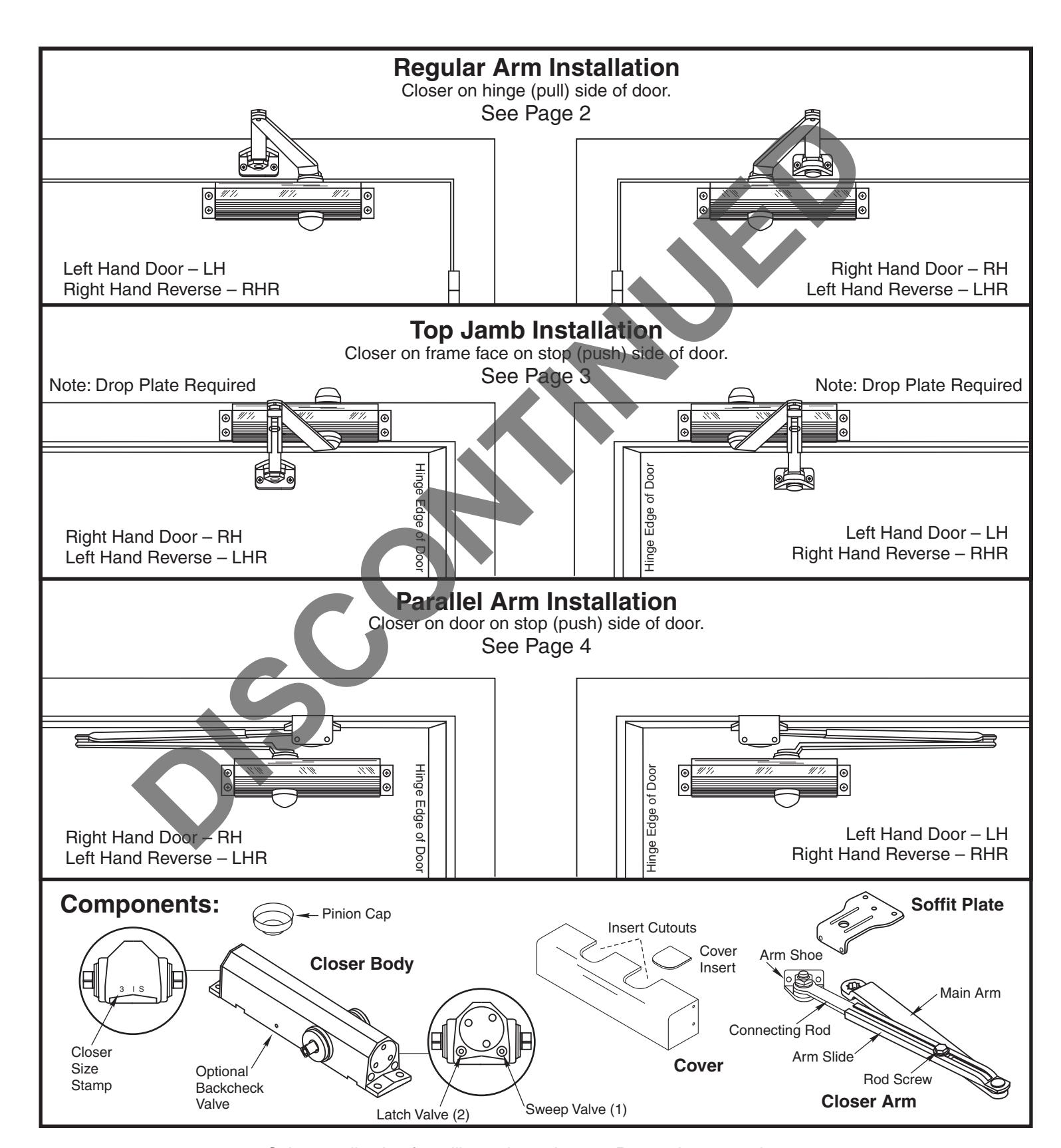
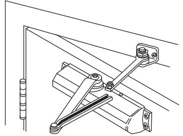
Regular Arm Mount Installation
-
-
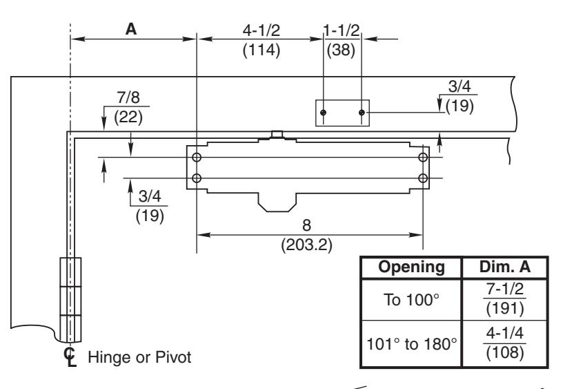
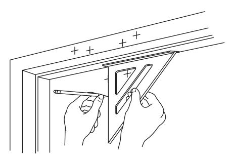
Select door opening angle.
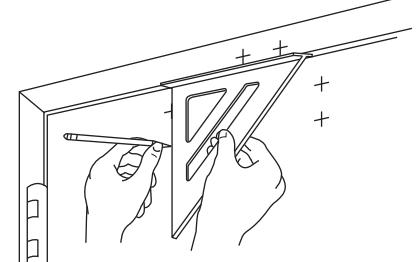
Use template to locate holes on door and frame:
- 4 on door on frame for closer. 2 face for arm shoe.
- - Prepare for fasteners. See Chart on Page 2.
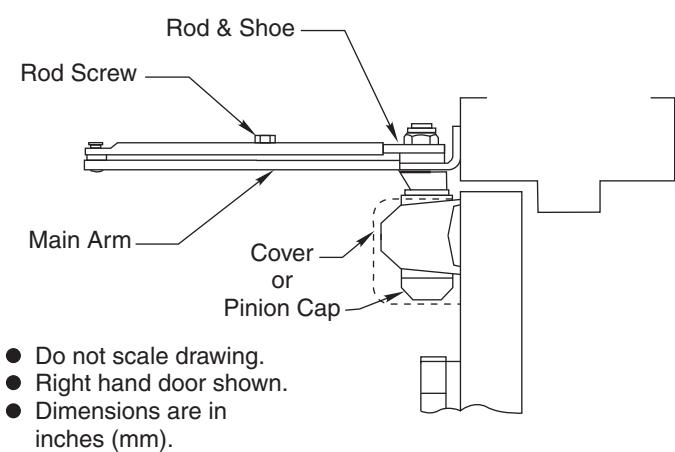
- - Remove rod and shoe from arm assembly.
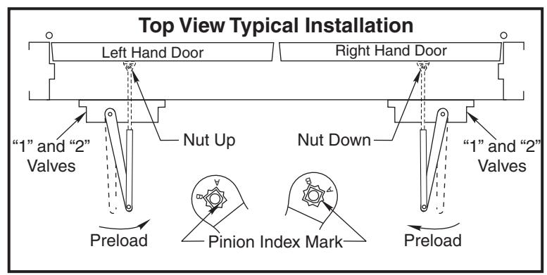
- Mount rod and shoe to frame. Up Right Hand Down Left Hand -Nut for door. Nut for door.
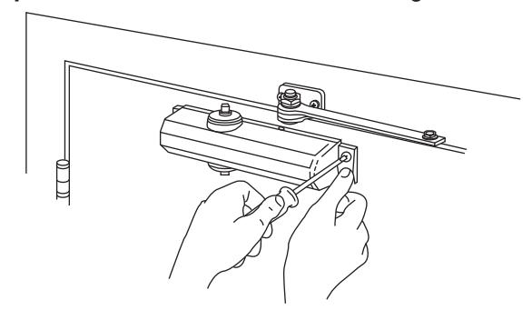
- - Mount closer to door. Place end with two regulating valves toward hinge edge of door.
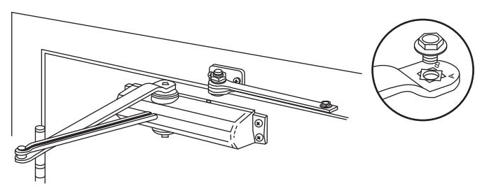
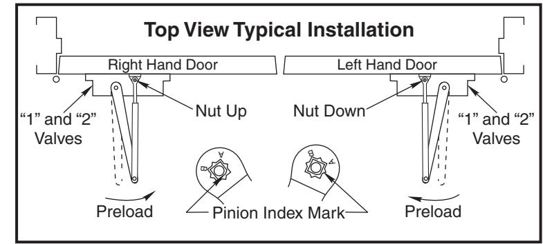
- Install main arm on closer. Place arm on pinion at 90 ° angle (perpendicular) to frame, see "Typical Installation" chart below. Fasten with arm screw.
- -90 Align and insert adjusting rod into adjusting tube. Close door. Adjust forearm at . Tighten rod screw. Open door slightly. ° angle (perpendicular) to door
- -See Page 3 ... Then install pinion cap or cover. Adjust closer.
| Fasteners Chart | |||
|---|---|---|---|
| Fasteners | Door or Frame | Drill-Sizes | |
| Standard |
#14 type "A" sheet
metal screw |
Wood | 7/32" (5.56 mm.) |
| 1/4" - 20 machine screw | Metal |
drill: #7 (0.201" dia.) Or 5.10mm
tap: 1/4" - 20 |
|
| Optional Sex nuts and bolts | Hollow-Metal |
9/32" (7.00 mm.) through;
3/8" (9.50 mm.) Door face opposite to closer |
|
|
Aluminum
or Wood |
3/8" (9.50 mm.) through | ||
|
Through-bolts and
grommet-nuts |
All |
9/32" (7.00 mm.) through;
3/8" (9.50 mm.) dia. x 3/8" (9.50 mm.) deep on door face opposite to closer |
|
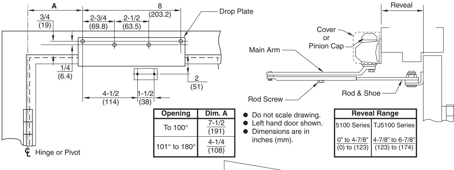
Top Jamb Mount Installation
Instructions
Drop Plate # 5146 5157

4 on frame face 2 on door for closer. for arm shoe.
- - Prepare for fasteners. See Chart on Page 2.
- - Remove rod and shoe from arm assembly.
- - Mount rod and shoe to door. Up Right Hand Down Left Hand Nut for door. Nut for door.
- - Fasten No. 5146 or 5157 drop plate to frame face.
- - Mount closer to drop plate. Place end with two regulating valves toward hinge edge of door.

- - Install main arm on closer. Place arm on pinion at 90 angle (perpendicular) to frame, see "Typical Installation" chart below. Fasten with arm screw. °
- - Reassemble arm. Adjust forearm at 90 ° angle (perpendicular) to door. Tighten rod screw.
- -See below for Hold Open, Closing Speed and Backcheck. Adjust closer.
Val e Adjustments v
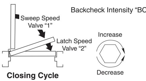
Decrease Opening Cycle Backcheck Backcheck Intensity "BC" Range
Closing Speeds "1" and "2"
- - Closing speed controlled by valve marked "1" (sweep range) and by valve marked "2" (latch range).
- - Backcheck Model Closers only Never close "BC" valve completely. suffix "BC". Backcheck controlled by va ve "BC". l
- - Hold Open Adjustment. Open door to angle of hold open desired. Tighten hold open adjustment nut with a 13/16" wrench or socket.
Installation Instructions
Parallel Arm Mount
- Remove rod and shoe from arm assembly.
- Fasten rod and shoe to soffit plate. Nut Up for Right Hand door. Nut Down for Left Hand door.
- Mount closer or drop plate and closer to door. Place end with two regulating valves toward lock edge of door.
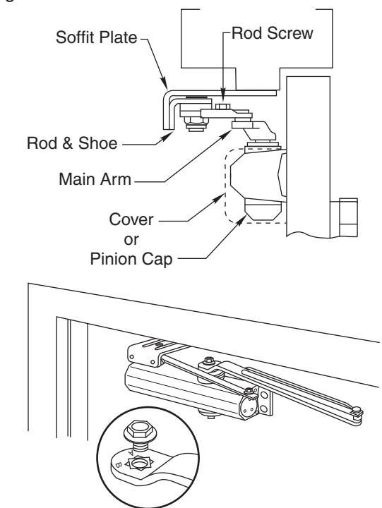
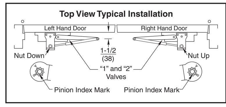
- Install main arm on closer. Rotate pinion 45° toward hinge edge of door to align main arm letter "A" (right hand) or "B" (left hand) with Pinion Index Mark, see "Typical Installation" this page. Tighten rod screw.
- Reassemble arm. Adjust forearm length to set arm elbow about 1-1/2 (38) from door. Tighten rod screw.
- Adjust closer. See Closer Adjustment on Pages 2 & 3.
Mount soffit plate to frame.
holes on door and frame:
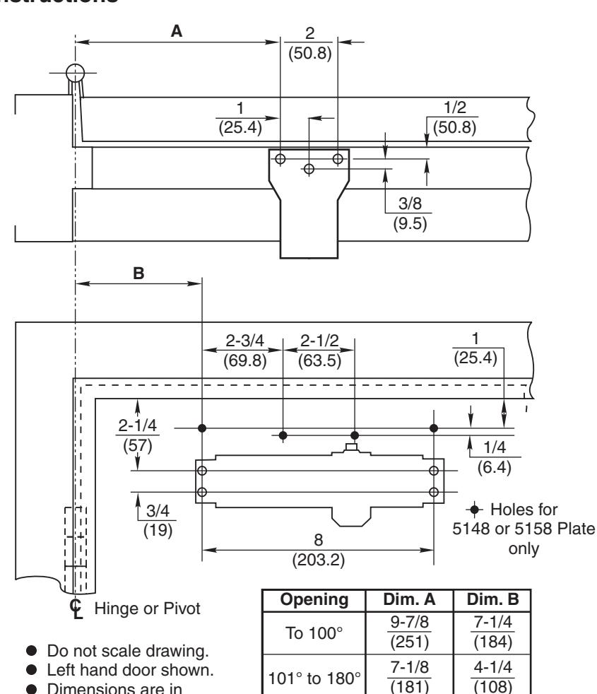
• Select door opening angle. Use template to locate
4 on door for closer (or drop plate).
3 on frame for soffit plate.
• Prepare for fasteners. See Chart on Page 2.
ASSA ABLOY, the global leader in door opening solutions
Dimensions are in inches (mm).
An ASSA ABLOY Group brand Yale ® is a registered trademark of Yale Security Inc., an ASSA ABLOY Group company. Copyright © 1987, 2008, Yale Security Inc., an ASSA ABLOY Group company. All rights reserved. 3000 Highway 74 East • Monroe, NC 28112 Reproduction in whole or in part without the express written permission of Yale Security Inc. is prohibited. Tel: (800)-438-1951 • Fax: (800)-338-0965 www.yalecommercial.com