ASSA ABLOY ACCENTRA 502F, 503F, 504F, 505F, 506F, 507F, 508F & 509F Trims Installation Instructions_80-8470-0502-000
Open the original PDF document
View PDF502F, 503F, 504F, 505F, 506F, 507F, 508F, & 509F
Trim
Installation Instructions

WARNING
This product can expose you to lead which is known to the state of California to cause cancer and birth defects or other reproductive harm. For more information go to www.P65warnings.ca.gov.
WARNING
Attention Installer: Any retrofi t or other fi eld modifi cation to a fi re rated opening can potentially impact the fi re rating of the opening, and ASSA ABLOY makes no representations or warranties concerning what such impact may be in any specifi c situation. When retrofi tting any portion of an existing fi re-rated opening, or specifying and installing a new fi re-rated opening, please consult with a code specialist or local code offi cial (Authority Having Jurisdiction) to ensure compliance with all applicable codes and ratings. 80-8470-0502-000 04/24
1-855-557-5078 Ext. 2 • www.accentra-assaabloy.com

502F, 503F, 504F, 505F, 506F, 507F, 508F, & 509F Trim Installation Instructions

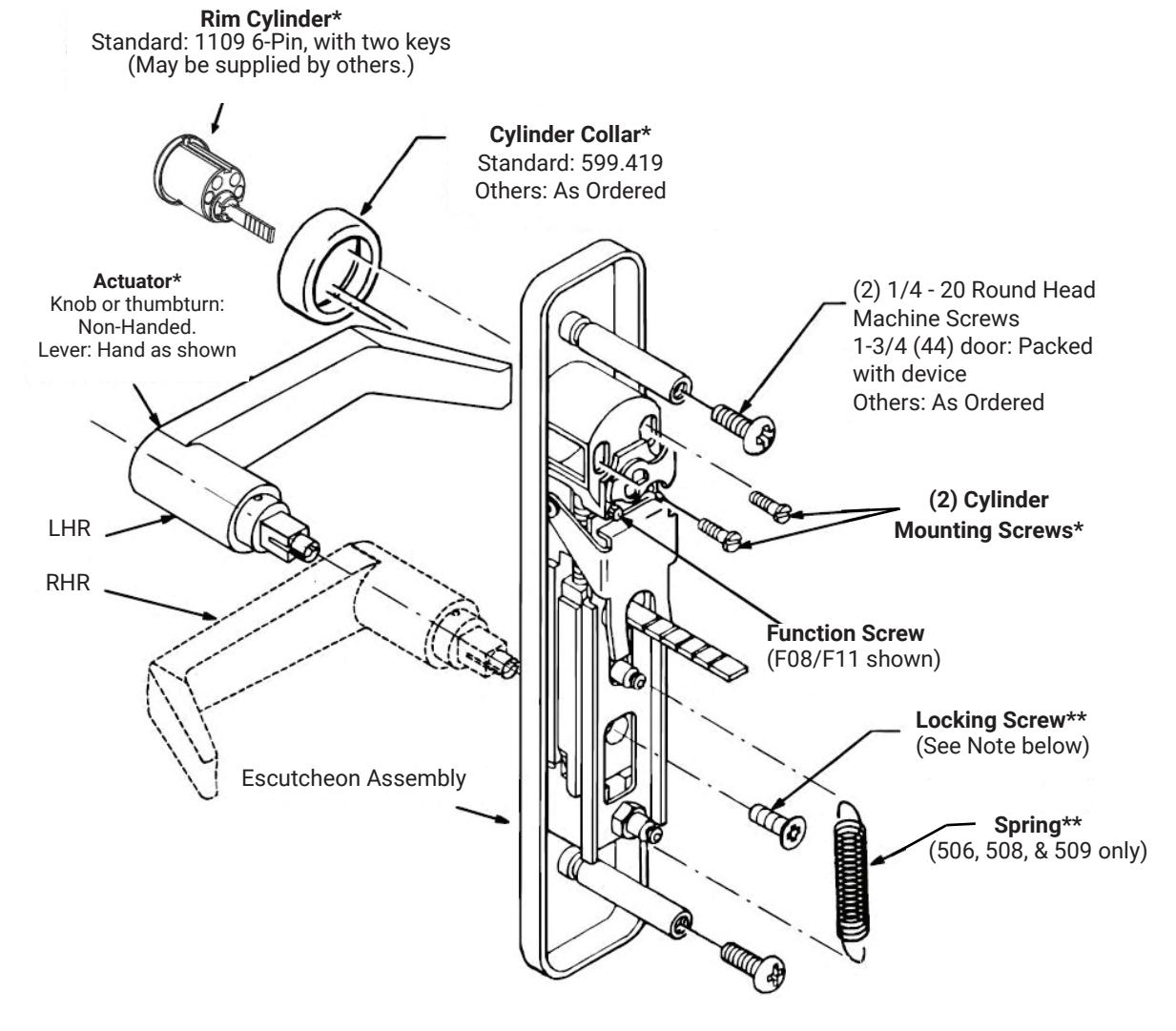
1. Assembly Instructions
Figure 1
Assembly Instructions
| Trim | Requirement | |
|---|---|---|
| 504F, 505F, 507F | None | |
| 506F, 508F, 509F | Check Hand (See Figure 1). To REVERSE HAND, remove and reassemble components marked (**), as shown. | |
| 502F, 503F | Assemble Cylinder (See instructions on page 6) | |
NOTE: When Locking Screw patch becomes worn or damaged, replace screw or use thread locking compound (available at auto parts stores).
NOTE: Knob and thumbturn trim are not handed. Lever trim is field reversible. In door pairs, knobs must be no less than 3-3/4" (95cm) on centers.
80-8470-0502-000 04/24
Trim
2. Installation Instructions
- A. Check box contents. (See page 3)
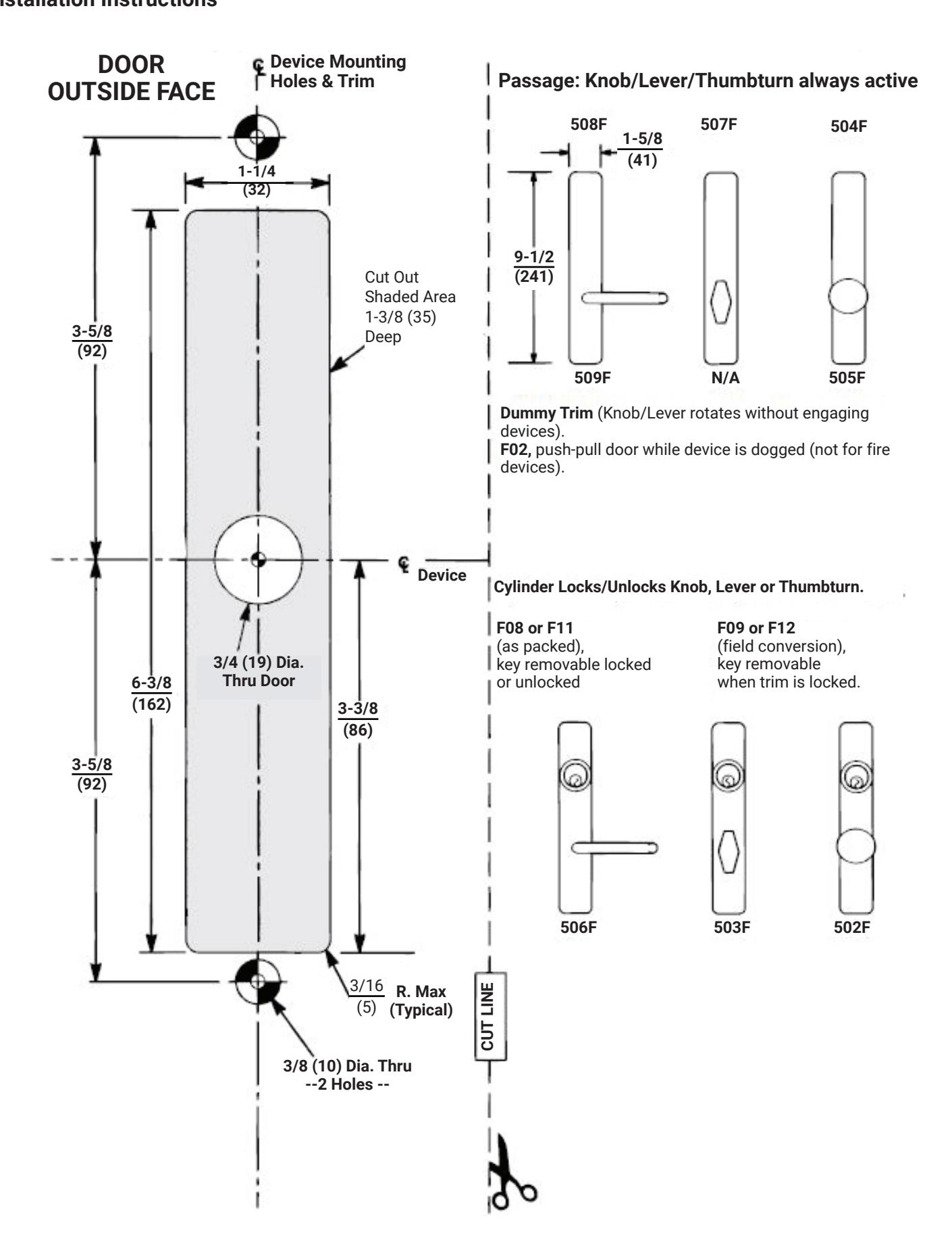
- B. Carry "Centerline of Device Mounting Holes" to outside door face. Follow steps A and B below.
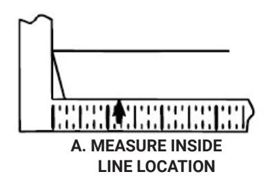
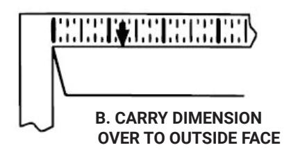
- C. Carry horizontal "Centerline of Device" from inside to outside door face.
- D. Align trim template and tape to door outside face.

Caution: Office copiers and facsimile machines may change the size of a drawing and make the template inaccurate to use as a door marker. If this is not the original template packed with the trim, use only the dimensions written on the template to locate the holes and cutout on the door. Do not use the template as a door marker.
- E. Spot holes and prepare door for trim.
- F. Mount trim to door. Fasten finger tight with two screws packed with device. (See Figure 2)
- G. With trim unlocked (tailpiece turning when lever is depressed or knob thumbturn is rotated), cut trim tailpiece as shown in Figure 3.
- H. Seat device so that trim tailpiece penetrates cam slot, as shown in Figure 3.
- I. Continue as shown in device instructions.
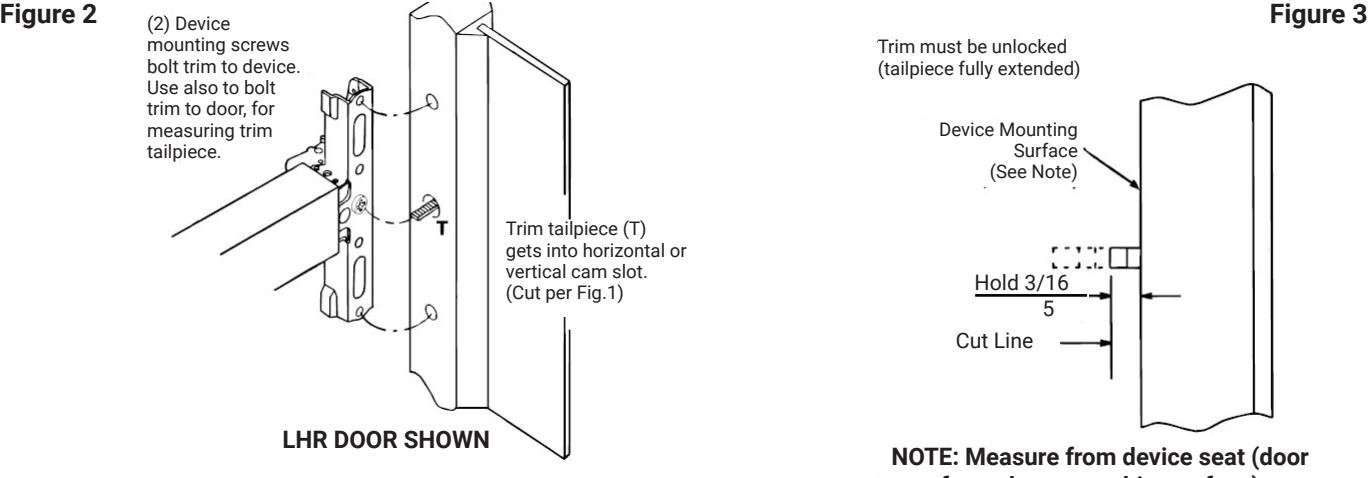
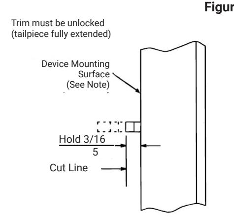
NOTE: Measure from device seat (door face-shown- or shim surface)
80-8470-0502-000 04/24
1-855-577-5078 Ext. 2 • www.accentra-assaabloy.com
502F, 503F, 504F, 505F, 506F, 507F, 508F, & 509F Trim Installation Instructions

3. Cylinder Assembly
A. Check cylinder components. See chart below. Non-standard cylinder collars and mounting screws must be supplied with optional cylinders.
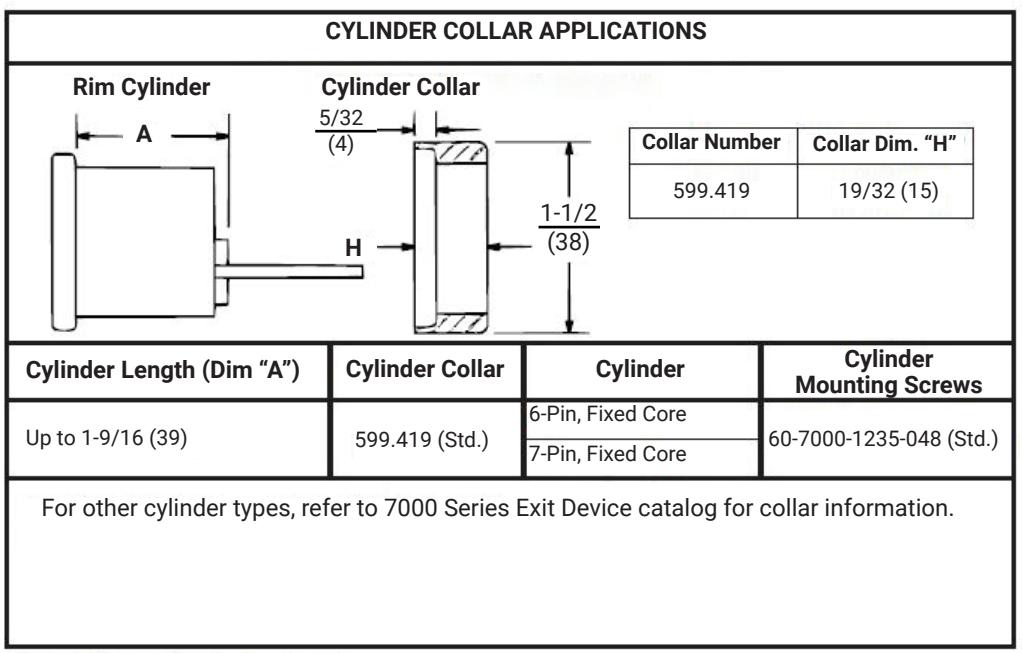
All dimensions are in inches (mm).
- B. Assemble cylinder, use components marked (*). Pass Cylinder tailpiece through Cylinder Collar and Cylinder Housing slot in cam. Bolt Cylinder seated in Cylinder Collar recess. Do not over tighten screws.
- C. Check cylinder action. Cylinder key must freely rotate tailpiece into lock (cam pushing locking lever down) and unlock (shown above) positions. When locking lever is engaged, it depresses the trim spindle. The lever/knob/thumbturn is then disengaged from the spindle.
- D. Cut Cylinder tailpiece (Not trim tailpiece). Correct length is 1/16" to 3/16" (2mm to 5mm) beyond Cylinder Housing cam.
- E. Determine trim function.
F08 & F11: As shipped. Key locks/unlocks knob/lever/thumbturn.
F09 & F12: Field move Function screw to Cylinder Housing hole under cam tip. Key locks/unlocks knob/lever/thumbturn. Key removable ONLY in locked position.

4. Trim Assembly Instructions
A. Check cylinder components.
NOTE: Cylinders longer than 1-1/4" (32) will require collars. Refer to cylinder collar chart.
|
Cylinder Collar
Chart |
||
|---|---|---|
| Cylinder Length | Collar | |
| 1-1/8" (29) | None | |
| 1-1/4" (32) | None | |
| 1-1/2" (38) | 1765.250** | |
**Specify Finish
- B. When required, cut cylinder tailpiece.
-
C. Assemble cylinder.
- Insert cylinder housing prongs into matching notches of escutcheon.
- 2. Pass cylinder tailpiece through cylinder collar (when required) and slot in cylinder housing cam.
- 3. Fasten cylinder using (2) mounting screws.
- 4. Do not over tighten screws.
-
D. Check cylinder action.
- Rotate cylinder tailpiece to cam the clutch lever down. This depresses the trim spindle assembly which disengages the trim spindle from the lever handle, putting the trim in a freewheeling, locked mode.
-
E. To change trim function:
- 1. Rotate cam tip to down positions (locked mode).
- 2. Move function screw as shown in figure 4.
Function Screw Position
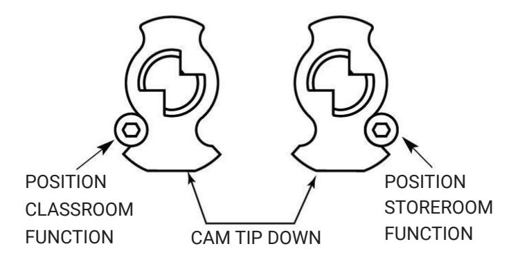
Figure 4