ASSA ABLOY ACCENTRA 4800LN Series Interconnected Locks Installation Instructions_80-9510-0056-010
Open the original PDF document
View PDF4800LN Series
ASSA ABLOY
Interconnected Lockset
Installation Instructions
Installation of this product requires that two 2 1/8" holes are spaced 4" apart center to center. See the hole template sheet for accurate hole locations.
A WARNING
This product can expose you to lead which is known to the state of California to cause cancer and birth defects or other reproductive harm. For more information go to www.P65warnings.ca.gov.
MARNING
Attention Installer: Any retrofit or other field modification to a fire rated opening can potentially impact the fire rating of the opening, and ASSA ABLOY makes no representations or warranties concerning what such impact may be in any specific situation. When retrofitting any portion of an existing fire-rated opening, or specifying and installing a new fire-rated opening, please consult with a code specialist or local code official (Authority Having Jurisdiction) to ensure compliance with all applicable codes and ratings.
80-9510-0056-010 01/24
4800LN Series
Interconnected Lockset Installation Instructions
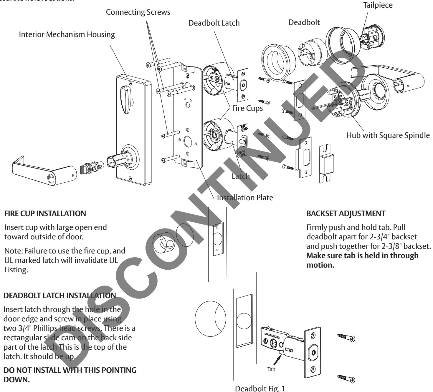
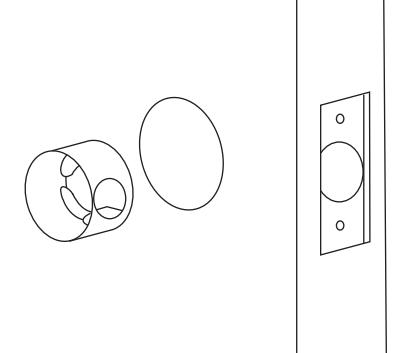
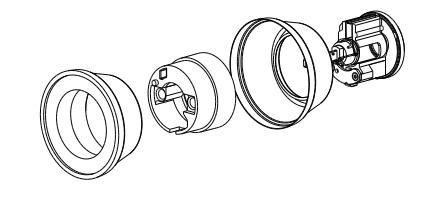
FIRE CUP INSTALLATION
Insert cup with large open end toward outside of door.
Note: Failure to use the fire cup, and UL marked latch will invalidate UL Listing.
FIRE CUP INSTALLATION
Insert cup with large open end toward outside of door.
Note: Failure to use the fire cup, and UL marked latch will invalidate UL Listing.

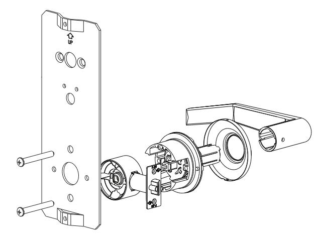
Exterior Assembly
There is a spring button on the tube of the assembly. It should point away from the door edge toward the hinge side of the door. For keyed entry levers, the release button should the hole in the neck of the lever. housing on the installation plate with point towards the door's edge. Insert the two self-thread screws saved the square spindle of the exterior Assembly/Verification before. Once this operation is done, assembly through the cam of the lower latch and insert the connecting screws loosely. Tighten these two screws.
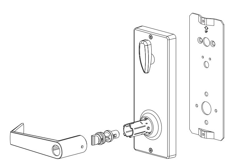
Lever Assembly
Line up the hole in the neck of the lever with the release button, then slide the lever until the button aligns with the hole. Using a key, nail, or other pointed tool, depress the button and push the lever onto the tube until the button snaps into the hole in the neck of the lever.
Assembly/Verification
Using a key from the exterior, operate the deadbolt latch to insure correct alignment. Operate the exterior lever insuring smooth operation. If the deadbolt or the exterior lever does not operate smoothly, adjust the installation plate up and down or side to side to find the correct position then tighten all four connecting screws.
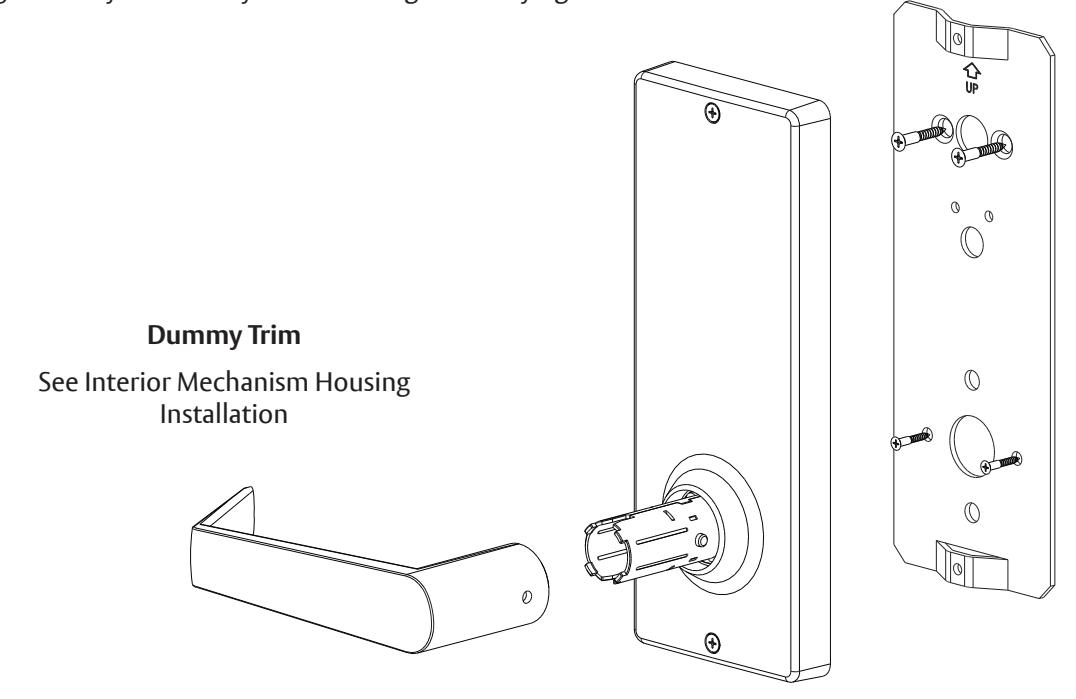
Interior Mechanism Housing
Reinstall the interior mechanism housing on the installation plate with the two self-thread screws saved before. Once this operation is done, make sure the square spindle for the interior mechanism housing is inside the hub of the lower latch and operates the latch. Note that the thumbturn must be in the vertical position, then slide the lever over the bottom tube and proceed same as with the exterior assembly.
1-855-557-5078 • www.assaabloy.com
80-9510-0056-010 01/24
Copyright © 2023, 2024, ASSA ABLOY Access and Egress Hardware Group, Inc. All rights reserved. Reproduction in whole or in part without the express written permission of ASSA ABLOY Access and Egress Hardware Group, Inc. is prohibited.
4800LN Series
Interconnected Lockset
Installation Instructions
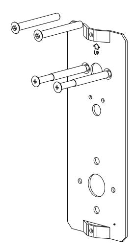

Unscrew the top and bottom screws from the interior mechanism housing and remove the installation plate. Save these screws to reinstall housing on the installation plate.
The exterior deadbolt assembly has a blade (tailpiece) attached to the rear of the cylinder. This tailpiece passes through the latch and engages the interior assembly. Insert the key in the cylinder so that the flat edge of the key is down and slide the tailpiece through the horizontal slot in the latch. Insert the deadbolt connecting screws through the installation plate and connect the plate with the exterior deadbolt housing. Slightly tighten these two screws. Deadbolt screws are 1/4" x 2-1/2" for 2" to 1-1/2" thickness doors. Use 1/4" x 2-1/16" screws also included for 1-3/8" thickness doors. DO NOT INSTALL WITH THE DEADBOLT EXTENDED.
INTERIOR MECHANISM HOUSING
Reinstall the interior mechanism housing on the installation plate with the two self-thread screws saved before. Once this operation is done, make sure the square spindle for the interior mechanism housing is inside the hub of the lower latch and operates the latch. Note that the thumbturn must be in the vertical position then slide the lever over the bottom tube and proceed same as with the exterior assembly.
NEW DOOR PREPARATION
NEW DOOR PREPARATION

- 2. Mark centers for all holes. Drill 1/8" (3mm) pilot holes at centers. Drill completely through door thickness.
- 3. Bore 2-1/8" (54mm) hole halfway through door. Finish bore from other side to prevent splintering.
- 4. To mark strike location, close the door and push locator pin through both guide holes marking the strike plates center position.
- 5. Bore 2 holes 1" (25mm) through the door edge.
- 6. For handleset installation only: Bore 5/16" hole to receive bottom portion of handleset.
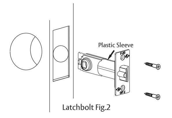
- 7. Insert the latch and then trace outlines of latchplates. Carefully chisel away outlined areas until plates fit flush. Drill pilot holes for latchplates mounting screws.
1. To prepare door frame for strike plates, locate the strike plates' center position. Marked on the stage 4 for "new door preparation".
- 2. Trace outlines of strike plates. Carefully chisel away outlined areas until plates fit flush.
- 3. With a 1" (25mm) drill bit, drill a 1" (25mm) deep hole at the upper strike plate to accept the bolt.
- 4. With a 1"(25mm) drill bit, drill a 1/2"(13mm) deep hole at the lower strike plate to accept the latch bolt.
- 5. Drill pilot holes for the plate mounting screws.
- 6. Secure the strike plates with (2) 3/4" screws.
80-9510-0056-010 01/24


Copyright © 2023, 2024, ASSA ABLOY Access and Egress Hardware Group, Inc. All rights reserved. Reproduction in whole or in part without the express written permission of ASSA ABLOY Access and Egress Hardware Group, Inc. is prohibited.

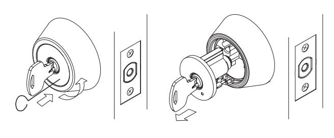
REMOVAL OF CYLINDER
When not installed on door
Remove the loose plate from theassembly. back of the cylinder. Two screws hold a metal strap in place. Under the "C" cutout in this strap is a semicircular indention in a spring loaded tab. Using the cylinder removing tool (wire with loop) or a screwdriver, place the tip of the tool against the tab in the indention and push toward the center and then clockwise. The purpose is to move the cylinder and strap to the left. When all the way left, push the cylinder out of the housing.
Note: it may be necessary to put the tool in between the gap created on the right and force the cylinder to the left. Remove the plug assembly from the cylinder housing for re-keying.
REMOVAL OF CYLINDER When installed on door
Insert the key into the plug. Press the cylinder removing tool into the hole positioned at 5 o'clock and turn the key counterclockwise. This will cause the face of the cylinder to rotate to the left slightly. Once turned off center, pull on the key to remove the cylinder. Remove the plug assembly from the cylinder housing for re-keying.