ASSA ABLOY ACCENTRA 4300 and 4300LN Series Tubular Knob Locks Installation Instructions_80-9150-0050-010
Open the original PDF document
View PDF4300 & 4300LN Series
ASSA ABIOY
Grade 2 Tubular Knob/Lever Locksets
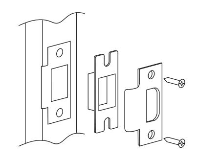
Installation Instructions
Attention Installer: Lock & Cylinder installation is critical (section 7 & 8). If installation instructions are not followed, this may result in damage to the lock and void the factory warranty.
IMPORTANT: The accuracy of the door preparation is critical for the proper functioning and security of this lock. Misalignment can cause premature wear and tear and a lessening of security.
Any retrofit or other field modification to a fire rated opening can potentially impact the fire rating of the opening, and ASSA ABLOY makes no representations or warranties concerning what such impact may be in any specific situation. When retrofitting any portion of an existing fire rated opening, or specifying and installing a new fire-rated opening, please consult with a code specialist or local code official (Authority Having Jurisdiction) to ensure compliance with all applicable codes and ratings.
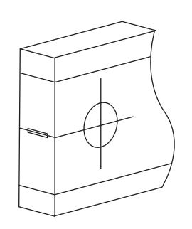
1. Mark door.
Mark horizontal line across edge of door for centerline of lock at desired height. Fold template over edge of door, centering on horizontal line. Mark centers of holes at proper backset.
Note: Be sure to verify backset before marking & drilling door.
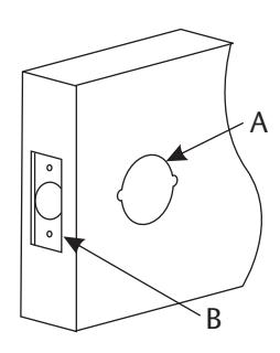
2. Drill door.
A. Drill 2-1/8" (54mm) dia. hole thru the door. Cut notches as shown on template.
Note: Dummy Trim requires 1/4" (6.4mm) hole one center line only.
B. Drill 1 (25mm) dia. hole in edge of door. Cut out for latch front 5/32" (4mm) deep. 1-1/8" (29mm) wide or 1" (25mm) wide x 2-1/4" (57mm) high. Check latch unit for proper width front.
Note: To avoid splintering wood doors, drill holes from both sides of the door.
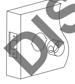
3. Install fire cup.
A. Insert cup with large open end toward outside of door.
Note:
Failure to use the fire cup, and UL marked latch will invalidate UL Listing.
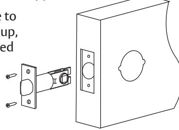
Install latch unit.
Insert latch unit in door. (Be sure bevel edge of bolt faces strike plate.) Attach with two screws supplied.
Note: Failure to use the fire cup. and UL marked latch will invalidate UL Listing.
5. Install strike.

WARNING
This product can expose you to lead which is known to the state of California to cause cancer and birth defects or other reproductive harm. For more information go to www.P65warnings.ca.gov.

WARNING
Attention Installer: Any retrofit or other field modification to a fire rated opening can potentially impact the fire rating of the opening, and ASSA ABLOY makes no representations or warranties concerning what such impact may be in any specific situation. When retrofitting any portion of an existing fire-rated opening, or specifying and installing a new fire-rated opening, please consult with a code specialist or local code official (Authority Having Jurisdiction) to ensure compliance with all applicable codes and ratings.
80-9150-0050-010 01/24
4300 & 4300LN Series
Grade 2 Tubular Knob/Lever Locksets Installation Instructions
6. Disassemble lock.
A. Remove inside lever or knob and rose (depress the retainer button on the neck of the inside assembly with screwdriver).
B. Pull lever or knob away from inside rose support.
7. Install outside lever or knob.
A. Insert outside lever or knob with square spindle into latch.
Note: Locking bar shaft must be in horizontal position as in drawing.
8. Install cylinder.
Depress retainer button in outside lever and remove lever. If cylinder is already installed, it must be unlocked to depress retainer button (insert key and rotate 90 degrees to unlock).
B. For knobs only: Slip collar onto shaft and align small hole with retainer button.
C. Insert cylinder into outside lever or knob shaft. For storeroom function, first rotate key 90 degrees.
D. Slip knob or lever onto shaft and align small hole with retainer button. Depress retainer button and push knob or lever into position.
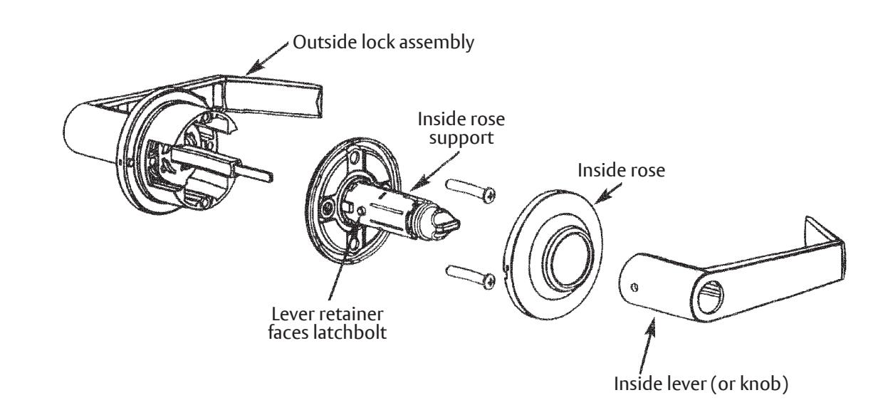
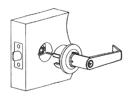
9. Install inside assembly.
A. Slip inside assembly over locking bar (turn button must be in vertical position).
B. Insert screws through inside mounting plate and tighten evenly until secure. Note: Retainer pin and lever must be located toward the jambs of the door.
C. Slip knob or lever onto shaft aligning small hole with retainer button. Depress retainer button and push knob or lever into position.
Storeroom Function
- Latchbolt operated by inside lever, key in outside lever.
- Outside lever always locked. Rotate key 90 degrees clockwise to unlock lever. Lever retracts latchbolt, rotate key to relock.
Classroom Function
- Either lever operates latchbolt (except when outside lever is locked by key).
- Rotate key 360 degrees counterclockwise to unlock lever. Rotate 360 degrees to relock lever.
- Inside lever always active.
80-9150-0050-010 01/24
4300 & 4300LN Series
Grade 2 Tubular Knob/Lever Locksets Installation Instructions