ASSA ABLOY ACCENTRA 428F Series Trim Installation Instructions_80-8470-0428-000
Open the original PDF document
View PDFTrim
Installation Instructions

For use with ASSA ABLOY ACCENTRA™ 7000, 2100, 1800 and 1500 Series Exit Device (Wood and Metal Doors)
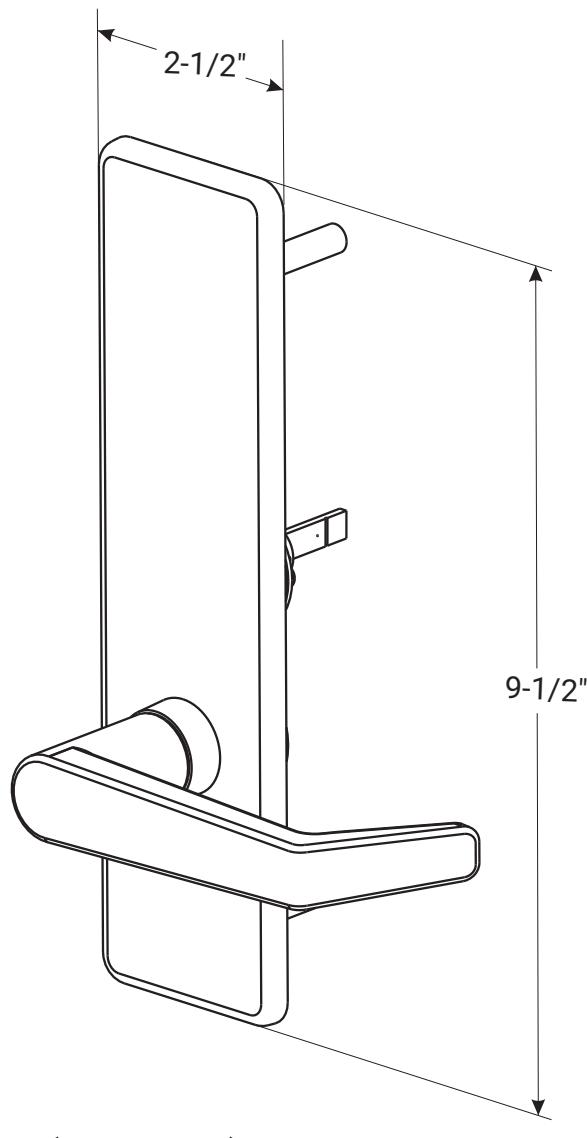
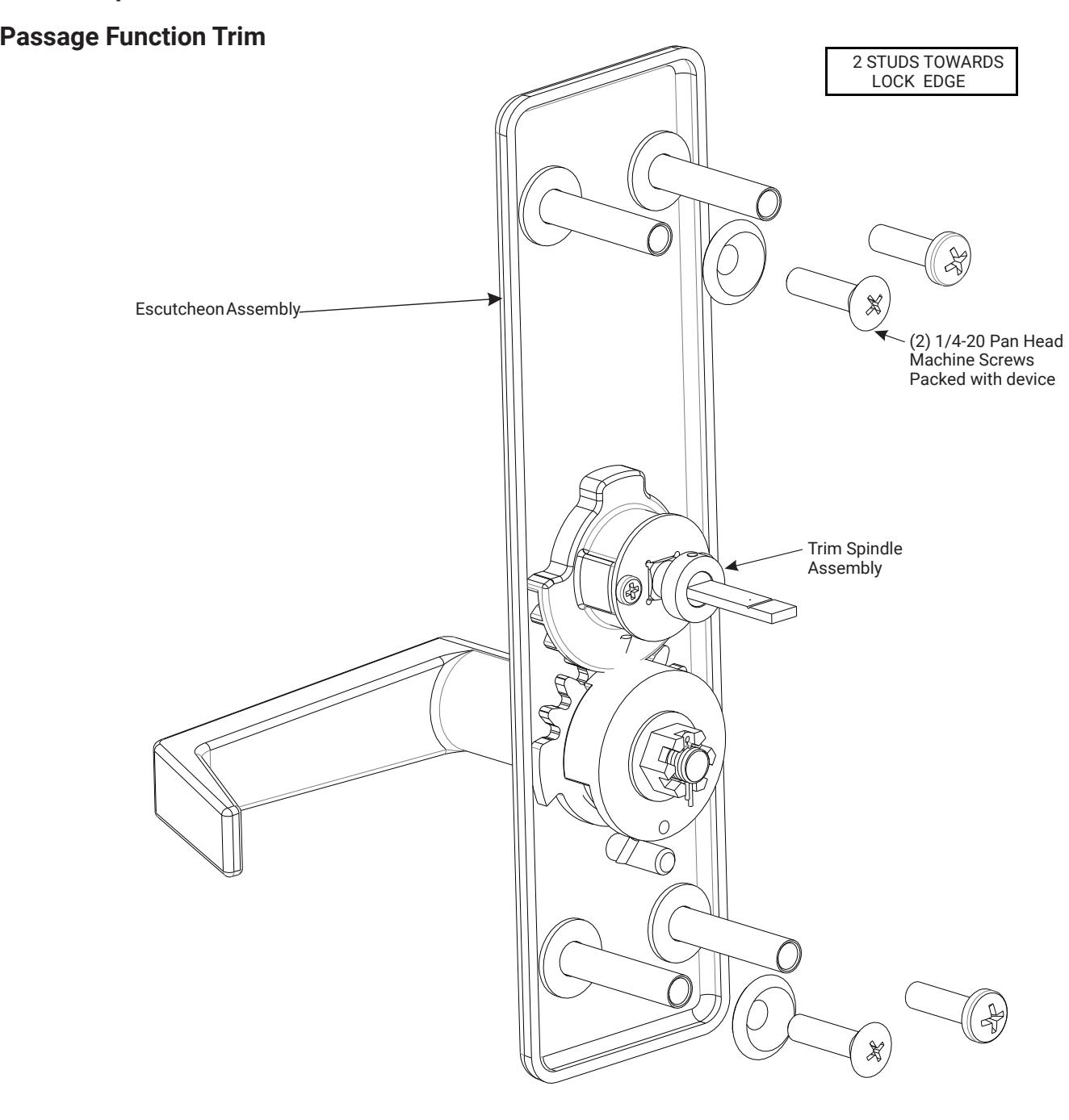
428F Series Passage Function Trim Handed (RHR or LHR) Lever Always Active
WARNING
This product can expose you to lead which is known to the state of California to cause cancer and birth defects or other reproductive harm. For more information go to www.P65warnings.ca.gov.
WARNING
80-8470-0428-000 04/24 Attention Installer: Any retrofit or other field modification to a fire rated opening can potentially impact the fire rating of the opening, and ASSA ABLOY makes no representations or warranties concerning what such impact may be in any specific situation. When retrofitting any portion of an existing fire-rated opening, or specifying and installing a new fire-rated opening, please consult with a code specialist or local code official (Authority Having Jurisdiction) to ensure compliance with all applicable codes and ratings.
1-855-557-5078 Ext. 2 • www.accentra-assaabloy.com

428F Series Trim Installation Instructions
Trim
Installation Instructions

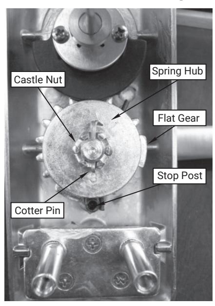
Trim Components

428F Series Trim Installation Instructions
How to Change Handing
426F, 427F and 428F Exit Device Trim

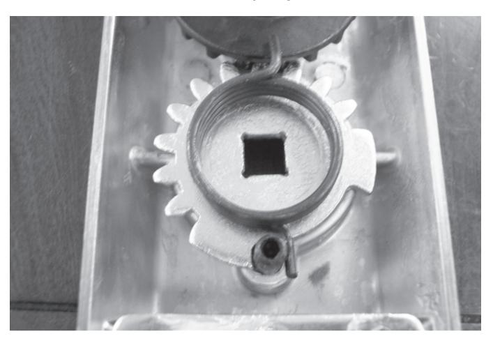
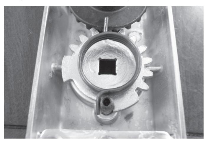
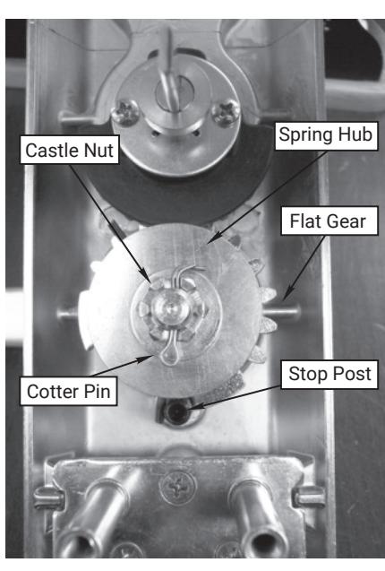
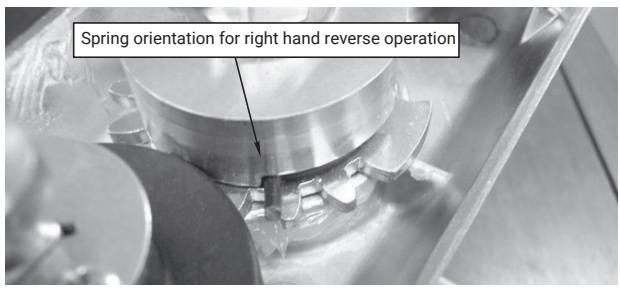
Right Hand Reverse Gear & Spring Orientation
Notes:
- 1. During change ensure black driven gear does not rotate.
- 2. Please wear safety glasses and be aware of spring tension on spring hub upon removal and assembly.
- 3. Light lubrication is recommended under flat gear, white lithium grease can be used.
Trim
Installation Instructions
To Change Hands:
Tools Needed: Needle Nose pliers, Crescent wrench.
LEFT HAND REVERSE RIGHT HAND REVERSE
- 1. Remove cotter pin.
- 2. Remove castle nut.
- 3. Remove washer.
- 4. Carefully pull up on spring hub to disengage spring.
- 5. Remove spring and note orientation.
- 6. Remove lever handle.
- 7. Pick-up flat gear, flip and orient stop opposite side of stop post. See pictures for orientation.
- 8. Install spring upside down from original orientation and place spring leg on opposite side of stop post from original installation orientation. See pictures for orientation.
- 9. Install lever 180 degrees from original position.
- 10. Install spring hub with stamped number in the 6 o'clock position.
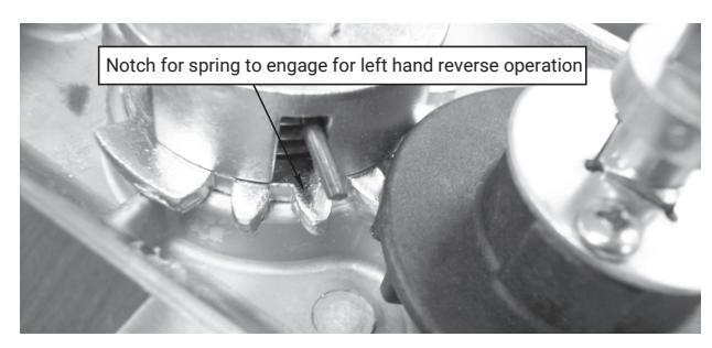
- 11. Rotate spring leg around with needle nose pliers to engage notch in spring hub, refer to pictures for reference position. Press down on spring hub to ensure complete engagement.
- 12. Install washer.
- 13. Install castle nut, do not over tighten, verify by insuring lever returns horizontally on its own.
- 14. Install cotter pin.
80-8470-0428-000 04/24

428F Series Trim Installation Instructions
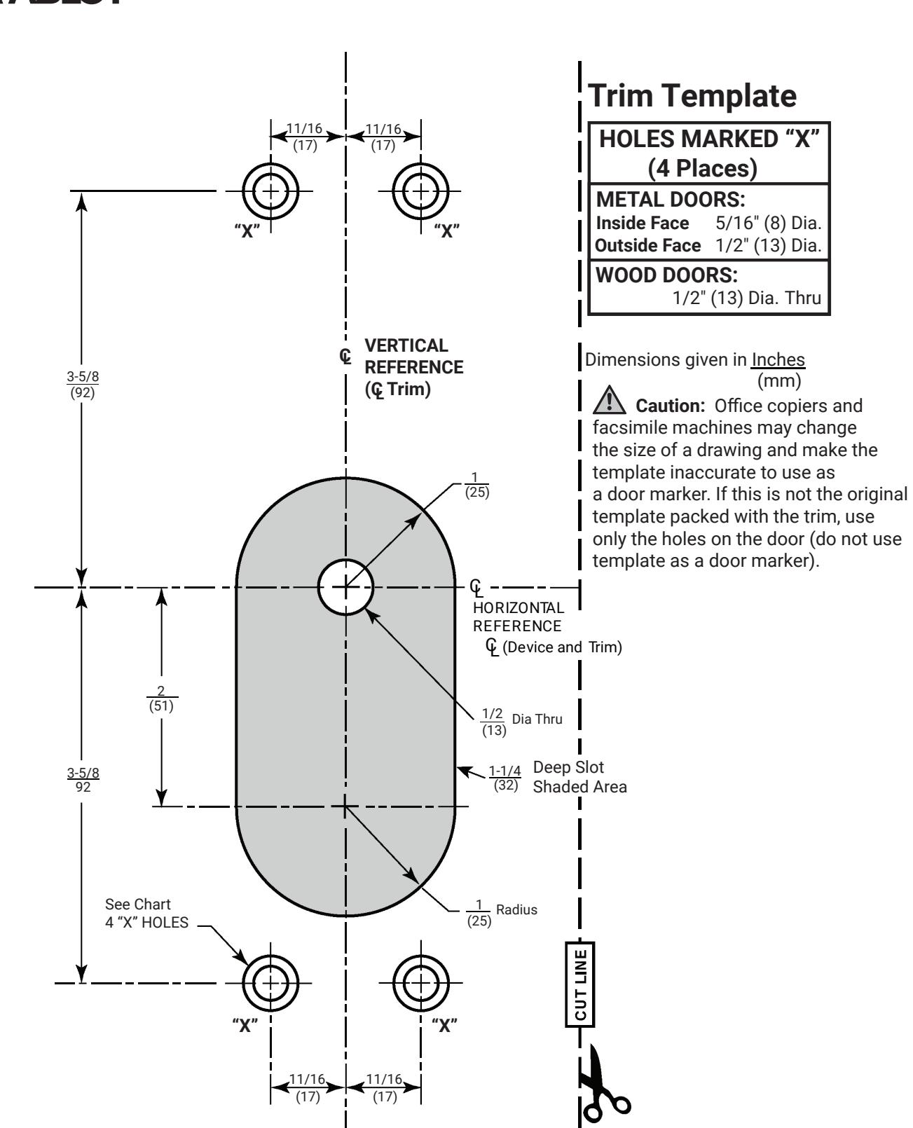
- 1. Check box for contents. See page 3 for components.
- 2. After marking door inside face for device location (Device Instructions), transfer Vertical Reference Centerline from inside to outside door face. Follow steps 2a and 2b below.
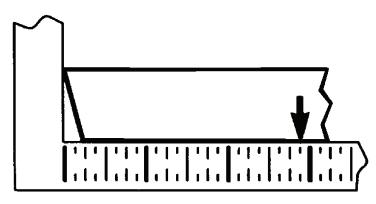
2a. Measure inside line location
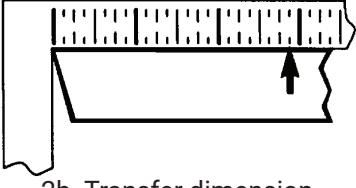
2b. Transfer dimension to outside face.
- 3. Transfer Horizontal Reference Centerline from inside to outside door face.
- 4. Align trim template and tape to outside door face. CAUTION: Office copiers and facsimile machines may change the size of a drawing and make the innacurate to use as door marker. If this is not the original template packed with the trim, use only the dimensions written on the template to locate the holes on the door (do not use the template as a door marker).
- 5. Spot holes and prepare door for trim.
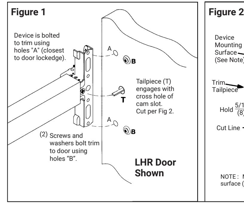
- 6. Mount trim to door thru holes "B". Fasten finger tight only with (2) screws and washers seating on door as shown in Figure 1.
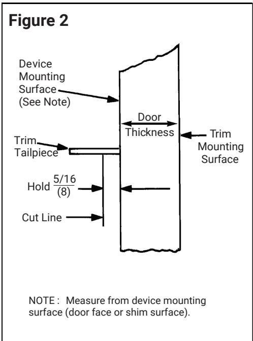
- 7. Cut trim tailpiece as shown in Figure 2.
- 8. Seat device so that trim tailpiece penetrates cam slot as shown in Figure 1. Continue as shown in device instructions.
80-8470-0428-000 04/24
Trim Installation Instructions

80-8470-0428-000 04/24
7