ASSA ABLOY ACCENTRA 428F Series Trim Installation Instructions_80-8421-0213-000
Open the original PDF document
View PDF213F, 214F, 217F
Trim
Installation Instructions

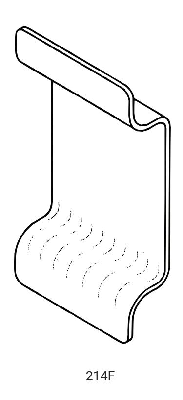
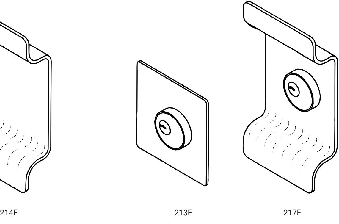
Dummy Trim F02: (Not for fire exit) Door pull when device is dogged.
F03: Key retracts bolt(s). NON-HANDED : Horizontal keyway
WARNING
This product can expose you to lead which is known to the state of California to cause cancer and birth defects or other reproductive harm. For more information go to www.P65warnings.ca.gov.
WARNING
80-8421-0213-000 04/24 Attention Installer: Any retrofit or other field modification to a fire rated opening can potentially impact the fire rating of the opening, and ASSA ABLOY makes no representations or warranties concerning what such impact may be in any specific situation. When retrofitting any portion of an existing fire-rated opening, or specifying and installing a new fire-rated opening, please consult with a code specialist or local code official (Authority Having Jurisdiction) to ensure compliance with all applicable codes and ratings.
1-855-557-5078 Ext. 2 • www.accentra-assaabloy.com
214F Trim: No preassembly required. Box should contain items marked *.
213F and 217F Trim: Assemble cylinder. Items marked * are used for installing trim to door.
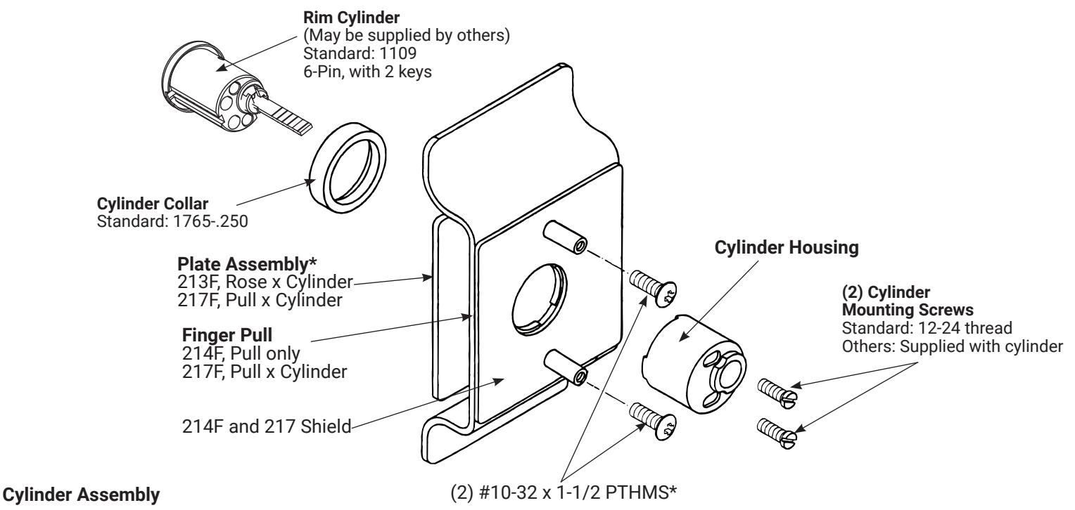
- 1. Check cylinder components. See chart. Non-standard cylinder collars and mounting screws must be supplied with optional cylinders.
- Assemble cylinder (note horizontal keyway). Insert Cylinder Housing prongs into Escutcheon matching notches. Pass Cylinder tailpiece thru Cylinder Collar and Cylinder Housing hole. Bolt Cylinder seated in Cylinder Collar recess (DO NOT OVERTIGHTEN SCREWS).
- 3. Check cylinder action. Cylinder key must freely rotate tailpiece when turned in either direction.
Cylinder Application
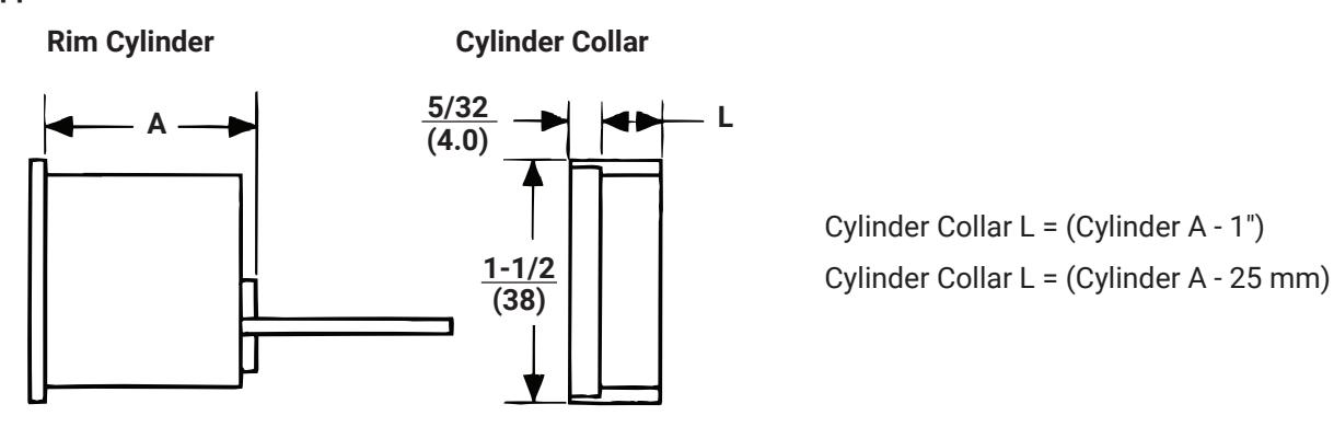
| ACCENTRA Cylinder | Cylinder Collar | Cylinder Mounting Screws |
|---|---|---|
| 6-Pin: Fixed Core | 1765.250 (STD.) | 60-7000-1235-048 (STD.) |
For other cylinder types, refer to 2100 series exit device catalog for collar information.
80-8421-0213-000 04/24
213F, 214F, 217F
Trim
Installation Instructions
ACCENTRA ASSA ABLOY
- 1. Check box contents. (See other side for box components and assembly instructions.)
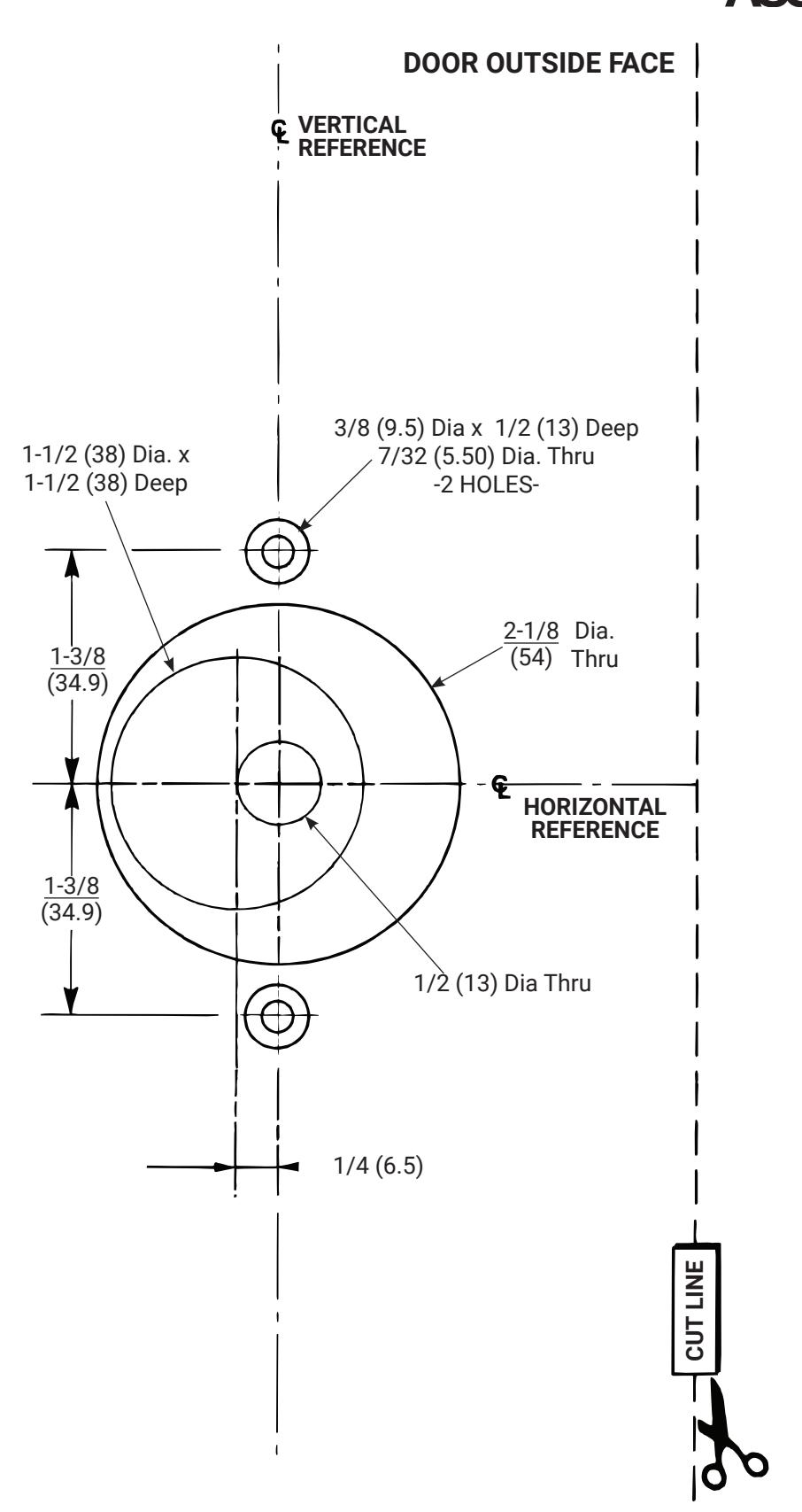
- 2. Carry Vertical Reference Centerline to outside door face. Follow steps A and B, in image to the right.
- 3. Carry Horizontal Reference Centerline from inside to outside door face STD 161 Door Prep Acceptable.
- 4. Align trim template and tape to door, outside face. Non-Handed Trim Installer preference for cylinder/key direction will determine position of 1/4" offset for cutout.
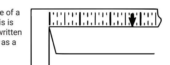
Caution: Office copiers and facsimile machines may change the size of a drawing and make the template inaccurate to use as a door marker. If this is not the original template packed with the trim, use only the dimensions written on the template to locate the holes on the door (do not use the template as a door marker).
- 5. Spot holes and prepare door for trim.
-
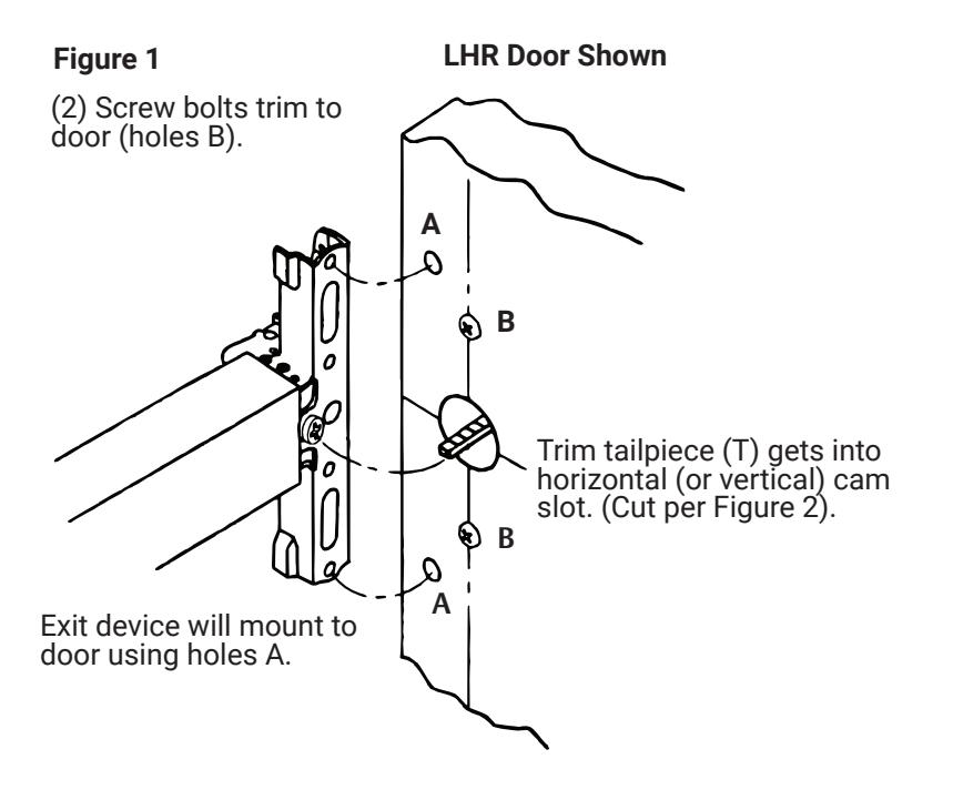
6. Mount trim to door. Fasten finger tight with 2 #10-32 x 1-1/2"PTH machine screws supplied (See Figure 1.)
- Note: If installing 214F dummy trim, continuie as shown in device instructions.
- 7. With trim in place, cut trim tailpiece as shown in Figure 2.
- 8. Seat device so that trim tailpiece penetrates cam slot, as shown in Figure 1. Continue as shown in device instructions.
A. Measure inside line location.
B. Carry dimension over to outside face
Trim for RHR or LHR door as packed.
Stock Doors:
Installation shows preparation for exit device trim. Stock door with ANSI/BHMA A156.115 preparation, for cylindrical lock with 2-3/4 (70) backset, may be used as substitute, when Trim is used with rim or SVR device.
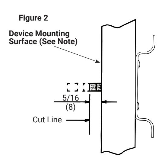
Note: Measure from device seat (door face - shown - or shim surface Dimensions are in inches (mm).
80-8421-0213-000 04/24
80-8421-0213-000 04/24