ASSA ABLOY ACCENTRA 4210, 4240, 4250 MPO (Support), Pull Side Installation Template_7342-1350
Open the original PDF document
View PDFNotes:
- Do not scale drawing.
- Right hand door shown. Same dimensions apply for left hand door, measured from centerline of hinge or pivot.
- Template information based upon use of 4-1/2 " hinges or 3/4 " offset pivots.
- Dimensions are shown in inches and millimeters (mm).
- Hollow metal doors require channel or box-type reinforcement when thru-bolt mount is specified.
- Sex-nuts are required for wood or plastic faced firedoor installations.
- Minimum thickness recommended for reinforcements in hollow metal doors and frames is .1046 (2.66) unless noted otherwise.
- Minimum ceiling clearance for closer unit is 4" (102).
- Maximum hinge side frame reveal is 1/8" (3) for Series 4210 and 4240.
| Preparation for Fasteners | |||||||
|---|---|---|---|---|---|---|---|
| Fasteners Door or Frame Drill-Sizes | |||||||
| Standard |
1/4" - 20 machine
screw |
Metal |
Drill: #7 (0.201" dia.)
Tap: 1/4" - 20 |
||||
| Sleeve nuts and bolts |
Hollow
Metal |
9/32" (7 mm) through;
3/8" (9.5 mm) door face opposite to closer |
|||||
| Aluminum or Wood | 3/8" (9.5 mm) through | ||||||
| Optional | Through-bolts and grommet-nuts | All |
9/32" (7 mm);
3/8" (9.5 mm) dia. x 3/8" (9.5 mm) deep on door opposite to closer |
||||
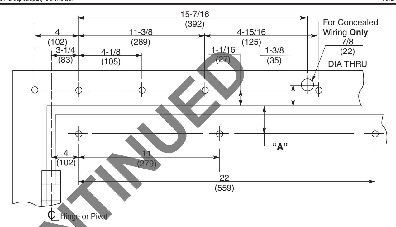
| Series | Arm Type | Max Degree of | Dim "A" | |
|---|---|---|---|---|
| Door Swing † | Hold Open | DIIII A | ||
| 4210 | Rigid | 180° | 175° | 1-3/16 (30mm) |
| 4240 | Connected-Free-Swing | 180° | 1-3/16 (30mm) | |
| 4250 | Double Egress | 140° ‡ | 135° | 1-13/16 (46mm) |
- † For doors swinging beyond 125°, buffer assembly should not be used. An auxiliary door stop is required.
- ‡ Door swing may be limited by frame or wall conditions.
Yale Series 4210 Rigid, 4240 Connected-Free-Swing, or 4250 Double Egress Slide Arm with Suffix MPO
Combination Door Closer-Holder and Releasing Device with Multi Point Hold Open Hinge (Pull) Side of Door Installation