ASSA ABLOY ACCENTRA 420F & 429F Series Trim Installation Instructions_80-8470-0420-000
Open the original PDF document
View PDFInstallation Instructions
For use with 7000, 2100, 1800 and 1500 Series Exit Devices (Wood and Metal Doors)
WARNING
This product can expose you to lead which is known to the state of California to cause cancer and birth defects or other reproductive harm. For more information go to www.P65warnings.ca.gov.
WARNING
Attention Installer: Any retrofit or other field modification to a fire rated opening can potentially impact the fire rating of the opening, and ASSA ABLOY makes no representations or warranties concerning what such impact may be in any specific situation. When retrofitting any portion of an existing fire-rated opening, or specifying and installing a new fire-rated opening, please consult with a code specialist or local code official (Authority Having Jurisdiction) to ensure compliance with all applicable codes and ratings.
80-8470-0420-000 04/24
Installation Instructions

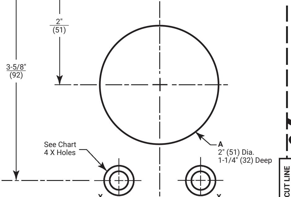
3-5/8" (92)
Outside Door Face
CL
Vertical Reference CL Trim
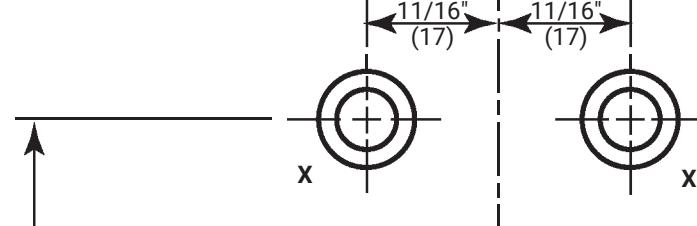
Trim Template Holes Marked X (4 Places)
Metal Doors:
Inside Face 5/16" (8) Dia. Outside Face 1/2" (13) Dia.
Wood Doors:
1/2" (13) Dia. Thru
Dimensions given in Inches
(mm)
| Trim | Holes |
|---|---|
| 420F | X |
| 429F | A, X |

CL
Caution:
Office copiers and facsimile machines may change the size of a drawing and make the template inaccurate to use as a door marker. If this is not the original template packed with the trim, use only the holes on the door (do not use template as a door marker).
11/16" (17)
X X
80-8470-0420-000 04/24
1-855-557-5078 Ext. 2 • www.accentra-assaabloy.com
11/16" (17)
Installation Instructions


Installation Instructions
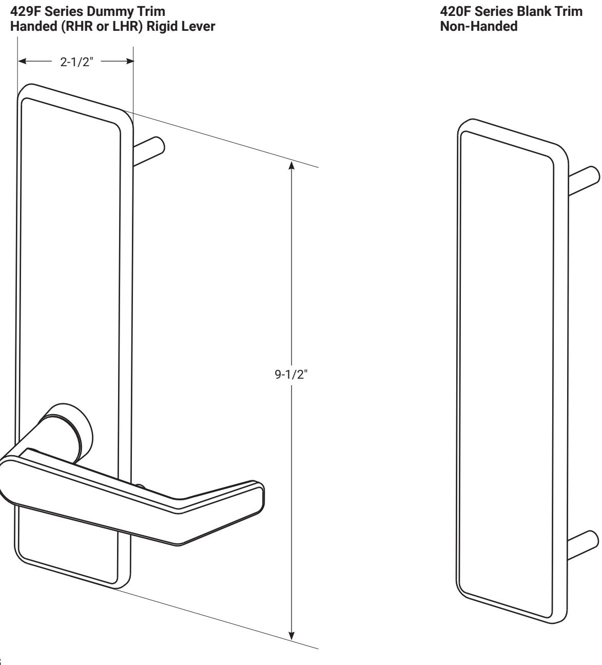
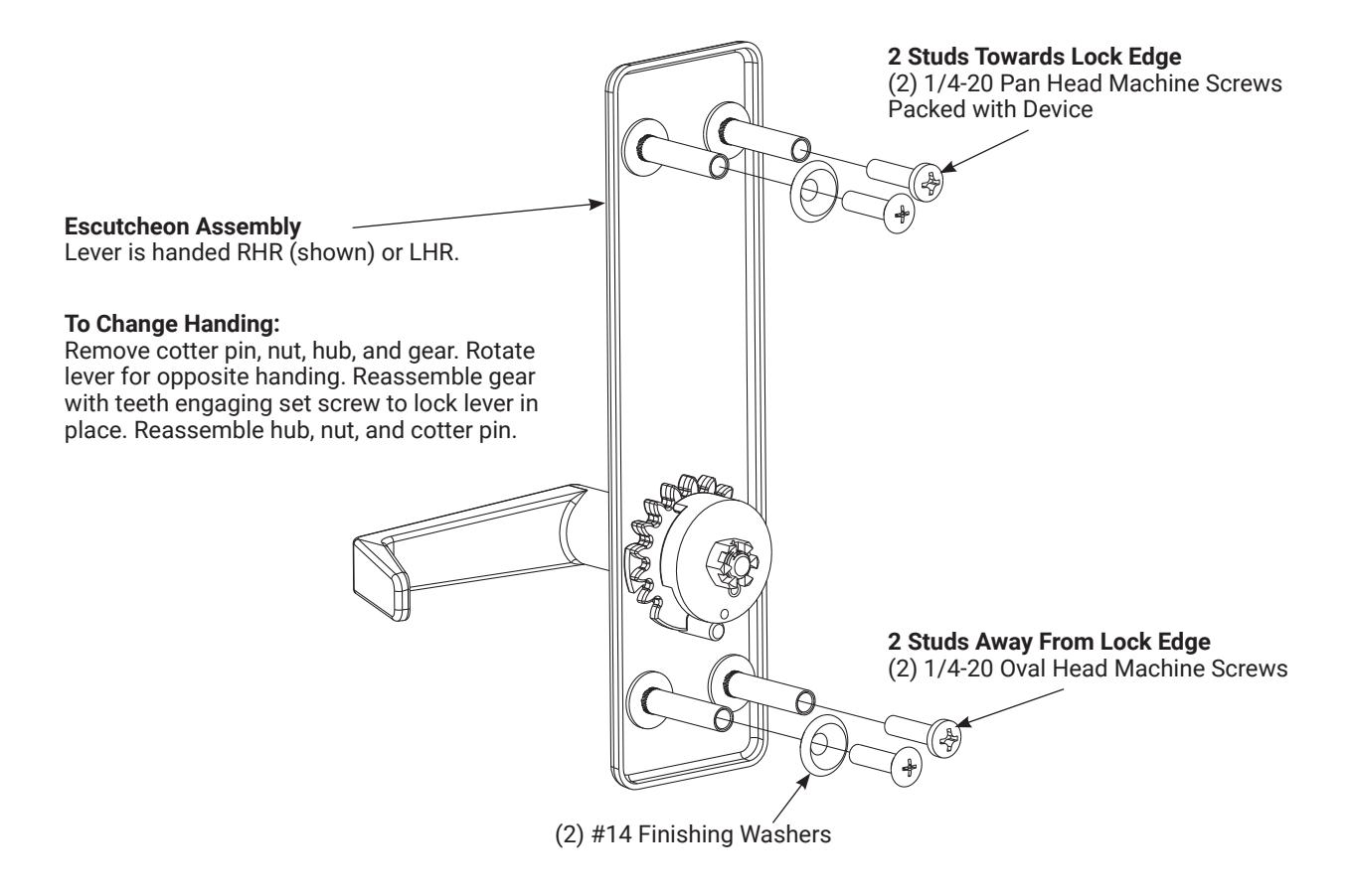
420F Series Blank Trim
Installation Instructions

429F Series Dummy Trim
5
1-855-557-5078 Ext. 2 • www.accentra-assaabloy.com
Installation Instructions
- 1. Check box for contents. See page 3 for components and instructions.
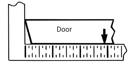
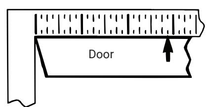
- 2. After marking door inside face for device location (Device Instructions), transfer Vertical Reference Centerline from inside to outside door face. Follow steps 2a and 2b below.
2a. Measure inside line location.
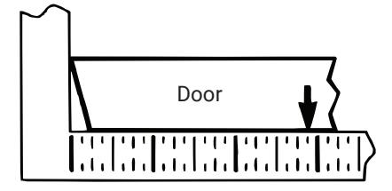
2b. Transfer dimension to outside face.
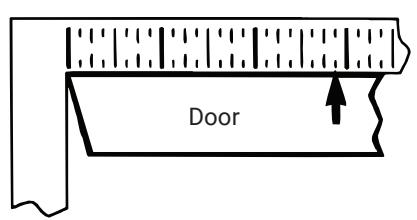
- 3. Transfer Horizontal Reference Centerline from inside to outside door face.
- 4. Align trim template and tape to outside door face. Caution: Office copiers and facsimile machines may change the size of a drawing and make the template inaccurate to use as a door marker. If this is not the original template packed with the trim, use only the holes on the door (do not use template as a door marker).
- 5. Spot holes and prepare door for trim.
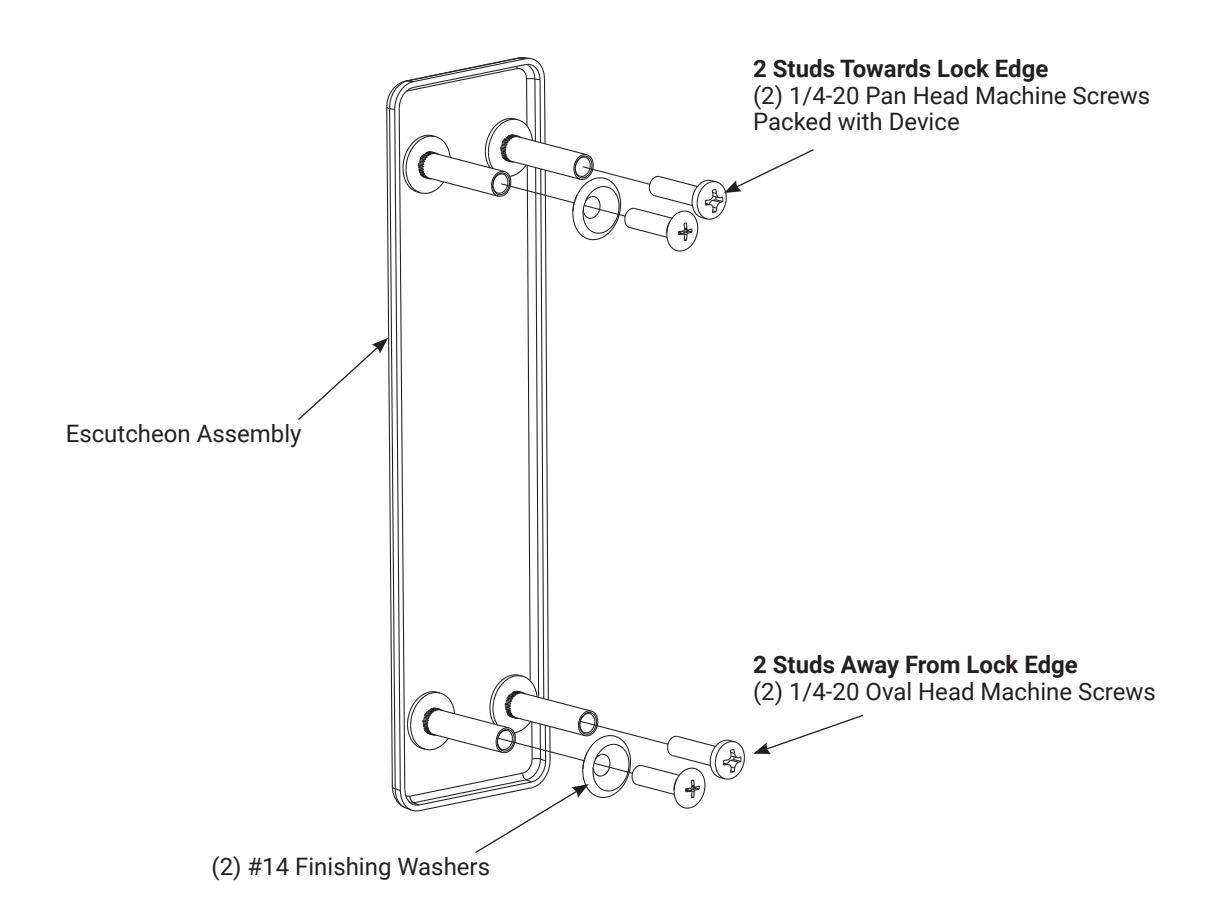
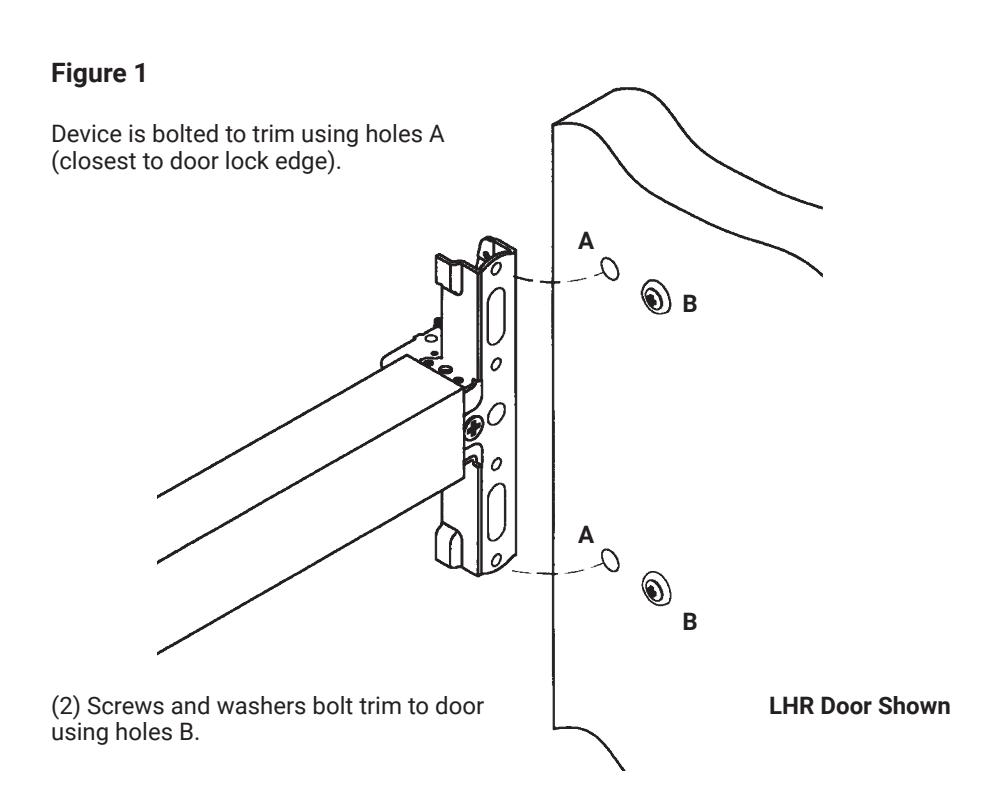
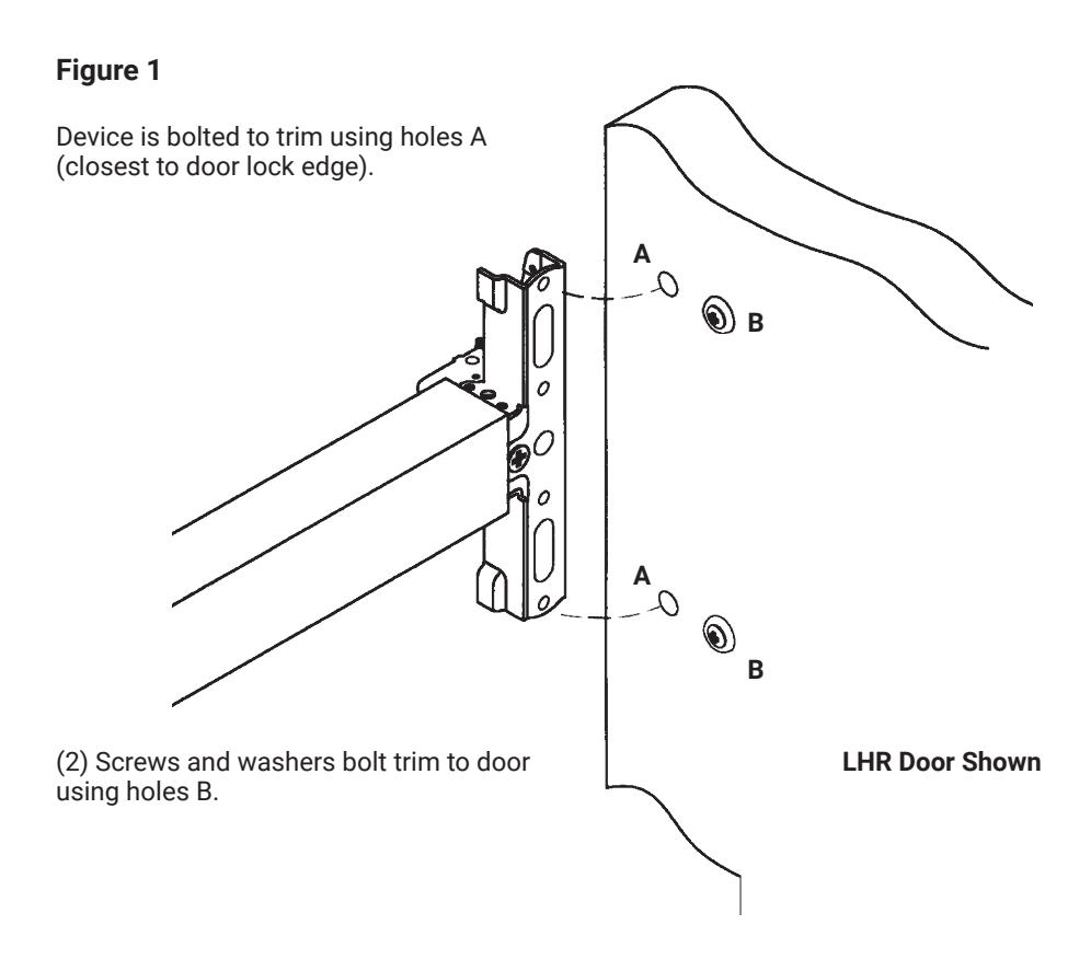
- 6. Mount trim to door thru holes B. Fasten finger tight only with (2) screws and washers seating on door as shown in Figure 1 .
- 7. Continue as shown in device instructions.
80-8470-0420-000 04/24
Installation Instructions

7
- 1. Check box for contents. See page 3 for components and instructions.
- 2. After marking door inside face for device location (Device Instructions), transfer Vertical Reference Centerline from inside to outside door face. Follow steps 2a and 2b below.

2a. Measure inside line location.
2b. Transfer dimension to outside face.
- 3. Transfer Horizontal Reference Centerline from inside to outside door face.
- 4. Align trim template and tape to outside door face.

Office copiers and facsimile machines may change the size of a drawing and make the template inaccurate to use as a door marker. If this is not the original template packed with the trim, use only the holes on the door (do not use template as a door marker).
- 5. Spot holes and prepare door for trim.
- 6. Mount trim to door thru holes B. Fasten finger tight only with (2) screws and washers seating on door as shown in Figure 1.
- 7. Continue as shown in device instructions.
80-8470-0420-000 04/24