ASSA ABLOY ACCENTRA 400ST, 4400ST, Slide Track, Push or Pull, Non-Hold Open & Hold Open_80-9344-0510-010
Open the original PDF document
View PDF

Installation Instructions
Slide Track Door Closers
80-9344-0510-010 (11-08)
CAUTION
An incorrectly installed or improperly adjusted door closer can cause property damage or personal injury.These instructions should be followed to avoid the possibility of misapplication or misadjustment.
Non Hold Open Models 400ST - 4400ST P400ST - P4400ST
Hold Open Models* 1400ST - 4410ST P1400ST - P4410ST
NOTE: For special applications a separate door and frame preparation template is packed with these instructions. Use this instruction sheet for installation sequence and closer adjustments only.
- For closers with or without closing feature suffix Delayed Action "DA"
- Use of an auxiliary door stop is always recommended.
* These units are not permitted to be installed in fire door assemblies.
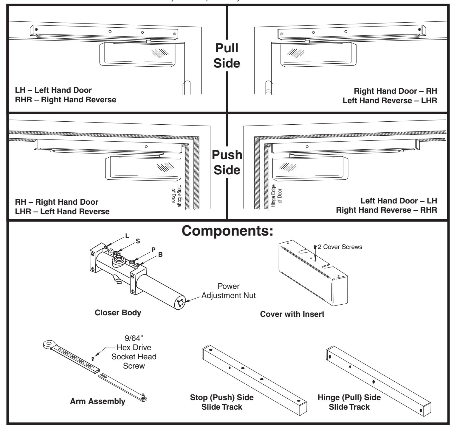
Pull Side Application
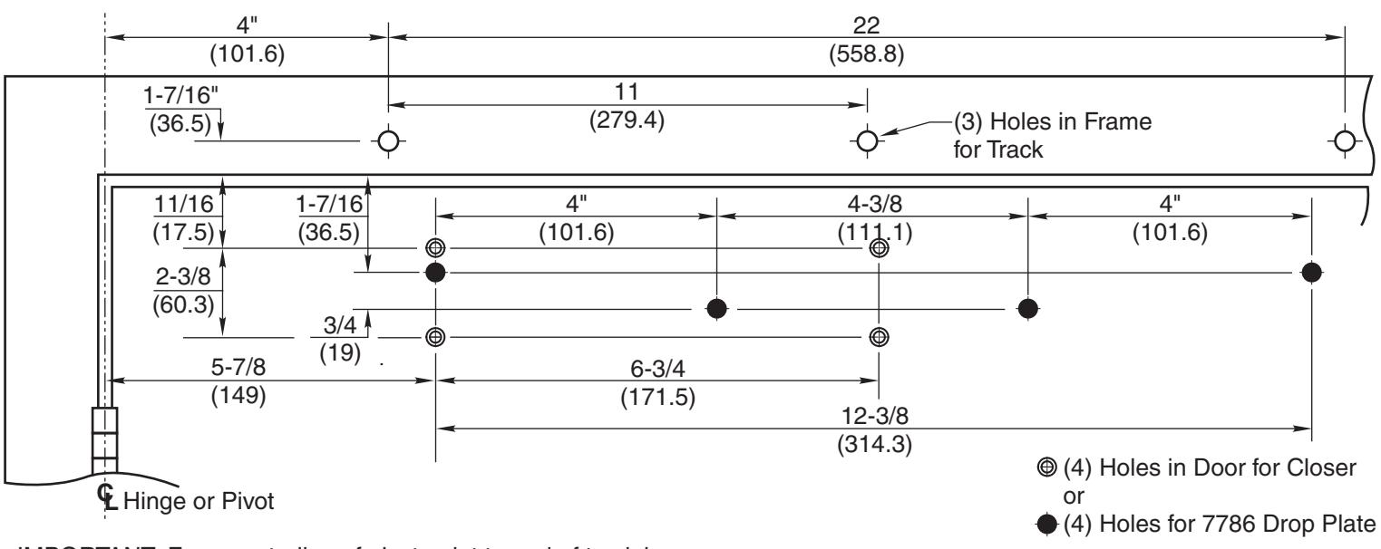
- IMPORTANT: From centerline of pivot point to end of track is 26-1/2" (673mm)
- Right hand door shown
- Do not scale drawing
- Dimensions are given in inches (mm)
- Min. ceiling clearance for unit is 2" (50mm) from frame rabbet
- 110° Max. Non Hold Open with Spring Buffer 180° Max. Non Hold Open without Spring Buffer
- 110° Max. – Hold Open
Installation Sequence:
-
1. Use template to locate holes on door and frame:
- 4 on door for closer or drop plate.
- 3 on frame face for track assembly.
- 2. Prepare door and frame for fasteners using chart on this page.
FOR 4400 SERIES MODELS ONLY set closer power for door size using chart below:
| Dimensions shown in inches (mm) | |||||||||
|---|---|---|---|---|---|---|---|---|---|
| Interior Doors | Exterior Doors | ||||||||
|
Maximum
Door Size |
30
(.76) |
36
(.91) |
42
(1.07) |
48
(1.22) |
30
(.76) |
36
(.91) |
42
(1.07) |
48
(1.22) |
|
|
Full Turns
Clockwise of Power Adjustment Nut |
0 | 2 | 5 | 8 | 2 | 5 | 8 | 11 | |
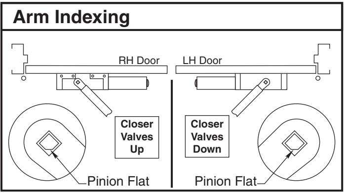
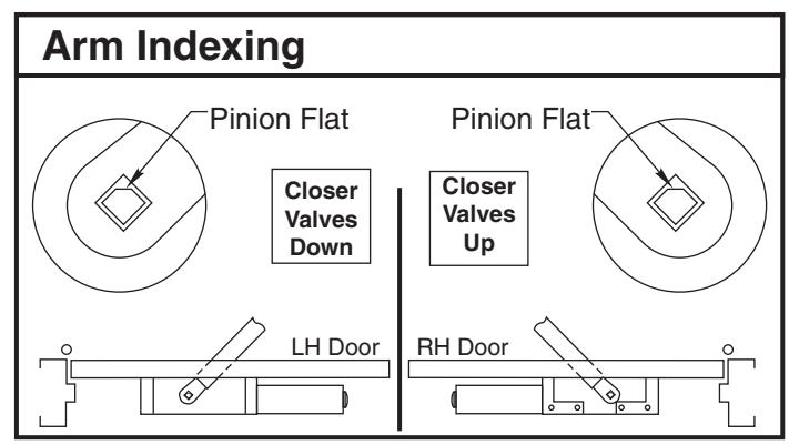
- 3. Fasten closer body to door with power adjustment nut toward lock edge of door and with valves UP for Right Hand door valves DOWN for Left Hand door
- 4. Fasten slide track to frame face with open side facing down and spring buffer end toward hinge edge of door.
| Preparation for Fasteners | |||||||
|---|---|---|---|---|---|---|---|
| Fasteners | Door or Frame | Drill-Sizes | |||||
| Standard | #14 Type "A" SM Screw | Wood |
3/16" (4.30 mm)
pilot hole required |
||||
| 1/4" - 20 machine screw | Metal |
Drill: #7 (0.201" dia.)
Tap: 1/4" - 20 |
|||||
| Optional | Sex nuts and bolts |
Hollow
Metal |
9/32" (7 mm) through;
3/8" (9.5 mm) door face opposite to closer |
||||
|
Aluminum
or Wood |
3/8" (9.5 mm) through | ||||||
|
Through-bolts and
grommet-nuts |
All |
9/32" (7 mm);
3/8" (9.5 mm) dia. x 3/8" (9.5 mm) deep on door opposite to closer |
|||||
- 5. Adjust arm to shortest length and install 9/64" hex drive socket head screw from screw pack.
- 6. Place slide arm on pinion shaft using Arm Indexing instructions above.
- 7. Secure arm with arm washer and arm screw.
- 8. Insert arm stud into slide block in track assembly. Secure by pushing in on the retainer clip that extends from the slide block in the track, until it is flush with the slide block.
- 9. Adjust closer. (See Page 4)
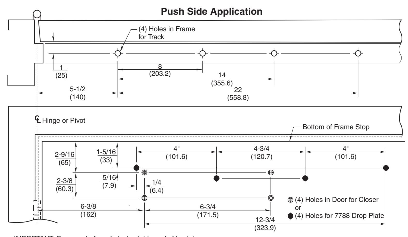
- IMPORTANT: From centerline of pivot point to end of track is 28" (711mm).
- Left hand door shown
- · Do not scale drawing
- Dimensions are given in inches (mm)
-
· Maximum door opening:
- 100° Max. Non Hold Open with Buffer in Track
- 125° Max. Non Hold Open without Buffer in Track, Auxiliary Door Stop Required
- 100° Max. Hold Open Track
Installation Sequence:
-
1. Use template to locate holes on door and frame:
- 4 on door for closer or drop plate.
- 4 on frame soffit for track assembly.
- 2. Prepare door and frame for fasteners using chart on Page 2.
FOR P4400 SERIES MODELS ONLY set closer power for door size using chart below:
| Dimensions shown in inches (mm) | ||||||||
|---|---|---|---|---|---|---|---|---|
| Interior Doors | Exterior Doors | |||||||
|
Maximum
Door Size |
30
(.76) |
36
(.91) |
42
(1.07) |
48
(1.22) |
30
(.76) |
36
(.91) |
42
(1.07) |
48
(1.22) |
|
Full Turns
Clockwise of Power Adjustment Nut |
0 | 2 | 5 | 8 | 2 | 5 | 8 | 11 |
-
3. Fasten closer body to door with power adjustment nut toward lock edge of door and with
- valves UP for Right Hand door valves DOWN for Left Hand door
- Fasten slide track to frame soffit with open side facing down and spring buffer end toward hinge edge of door.
- 5. Adjust arm to shortest length and install 9/64" hex drive socket head screw from screw pack.
- 6. Place slide arm on pinion shaft using Arm Indexing instructions above.
- 7. Secure arm with arm washer and arm screw.
- 8. Insert arm stud into slide block in track assembly. Secure by pushing in on the retainer clip that extends from the slide block in the track, until it is flush with the slide block.
- 9. Adjust closer. (See Page 4)
80-9344-0510-010 (11-08) Page 3
Adjustment Instructions
Arm Attachment to Track
Insert arm stud into slide block in track. Secure by pushing in on the retainer clip that extends from the slide block, until it is flush with the slide block.
Door Opening Angle and/or Hold Open Angle:
Remove 9/64" hex drive socket head screw from arm. Open door to desired angle and install hex-drive socket head screw into hole in adjusting rod that is aligned with the hole in the adjusting tube.
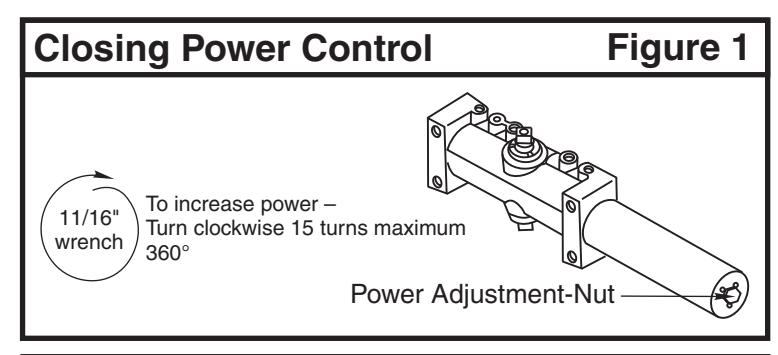
Closing Power
400ST Models come in three different sizes (4 thru 6), each power size can be increase by 50%.
4400ST Models are fully adjustable for proper sizing. See chart on page 2 or 3.
To adjust closer power - See Figure 1.
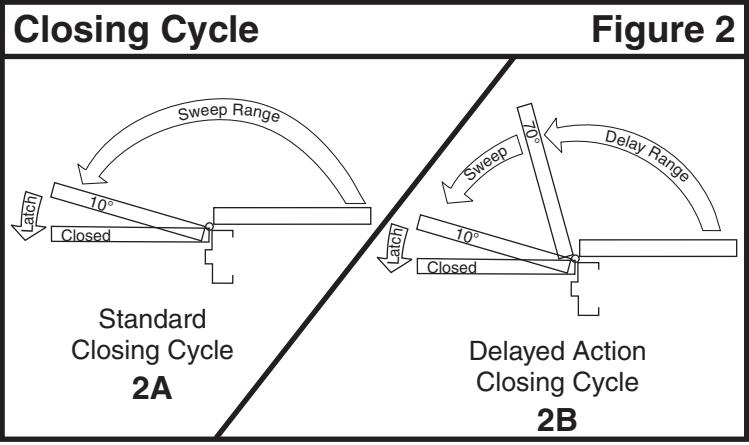
Closing Cycle (hydraulic control) Standard Closer Only
See Figure 2a.
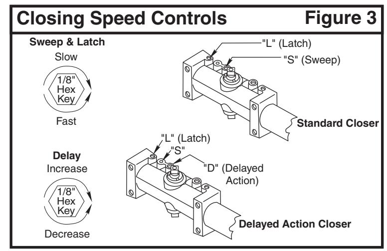
Valve "L" controls door speed in Latch range.
Valve "S/D" controls door speed in Sweep range.
Adjust as shown in Figure 3.
Delayed Action Closer Only
See Figure 2b.
Valve "L" controls door speed in Latch range.
Valve "S" controls door speed in Sweep range.
Valve "S/D" controls door speed in Delay range.
Adjust as shown in Figure 3.
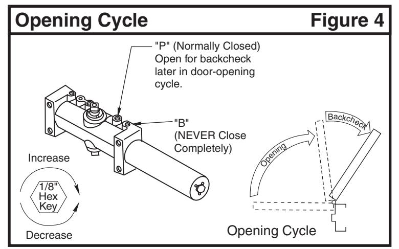
Opening Cycle (hydraulic control) See Figure 4.
Valve "B" cushions (slows) door opening in the backcheck range.
Valve "P" allows "backcheck" to begin later in the opening cycle.
Adjust as shown in Figure 4.
On/Off Hold Open Feature:
Slotted screw, accessible thru hole in face of track, engages or disengages the hold open feature with 1/4 turn of the screw. Hold open units are not permitted in fire door assemblies.
Hold Open Power Adjustment:
If more hold open power is required, the power may be increased by turning the adjustment screw in the end of the track nearest the hinges. Use 9/64" hex wrench provided and rotate adjustment screw clockwise to increase holding power.
Installation of Cover:
Fasten cover to closer with two screws provided:
Cover fastens at the top of closer