ASSA ABLOY ACCENTRA 400 Series, Regular, Top Jamb or Parallel Arms, Non-Hold Open Only Installation_80-9344-1101-010
Open the original PDF document
View PDF

An incorrectly installed or improperly adjusted door closer can cause property damage or personal injury. These instructions should be followed to avoid the possibility of misapplication or misadjustment.
CAUTION Non Hold Open Door Closers Models – 400 TJS400 TJ400 TJL400 PA400
Installation Instructions
80-9344-1101-010 (06-09)
- With or without suffix (Delayed Action) closing. "DL"
- With or without suffix with metal Cover. "M"
For Special Applications a separate door and frame preparation template is packed with these instructions. Use this instruction sheet for installation sequence and closer adjustments only. Note:
- It is recommended that the door, on which the door closer will be installed, be hung on ball bearing hinges. Door must swing freely.
- A separate door stop, supplied by others, is recommended to prevent damage to the door closer, closer arm; or to the door, frame or adjacent walls.
- Door and Frame must be properly reinforced, or use of special fasteners employed, to prevent the mounting screws from pulling out.
- All dimensions are given in inches with corresponding metric dimensions (millimeters) in parentheses.
|
Preparation for Fasteners
Figure 2 |
||||||
|---|---|---|---|---|---|---|
| Fasteners | Door or Frame | Drill-Sizes | ||||
| Standard |
#14 type "A"
S.M. screw Arm: 1-1/4" (32 mm.) Closer: 2-3/4" (70 mm.) |
Wood | 7/32" (5.56 mm.) | |||
| 1/4" - 20 machine screw | Metal |
drill: #7 (0.201" dia.)
tap: 1/4" - 20 |
||||
| Optional | Sex nuts and bolts | Hollow-Metal |
9/32" (7.00 mm.) through;
3/8" (9.50 mm.) on door face opposite to closer |
|||
|
Aluminum
or Wood |
3/8" (9.50 mm.) through | |||||
|
Through-bolts and
grommet-nuts |
All |
9/32" (7.00 mm.) through;
3/8" (9.50 mm.) dia. x 3/8" (9.50 mm.) deep on door face opposite to closer |
||||
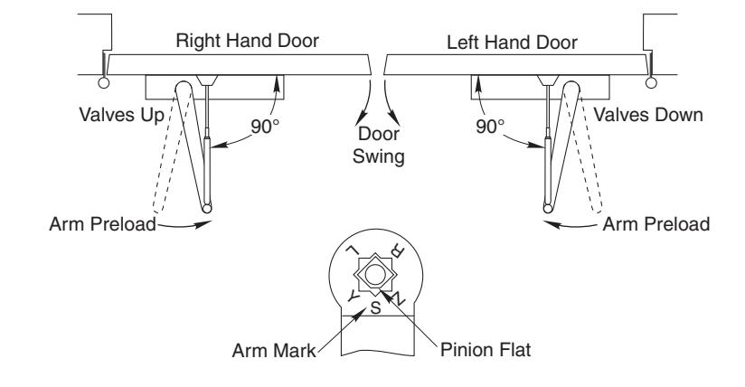
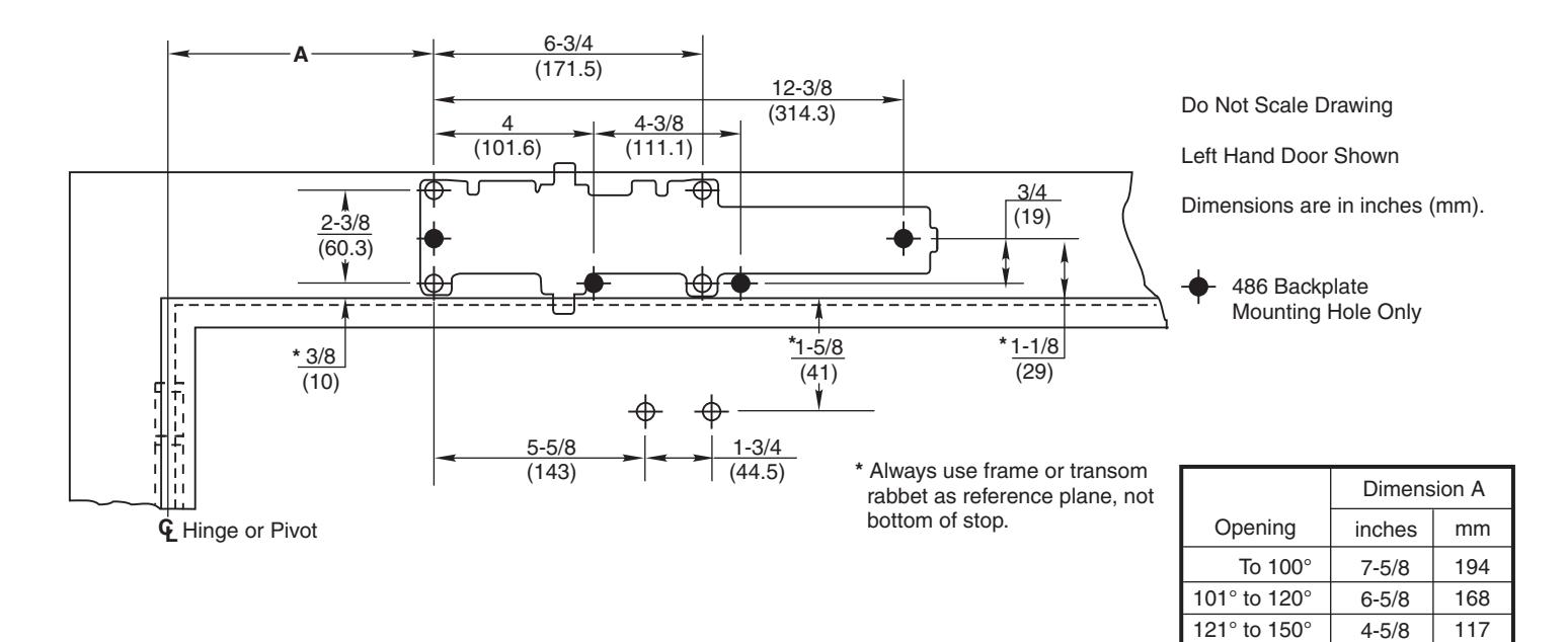
Regular Arm
Template
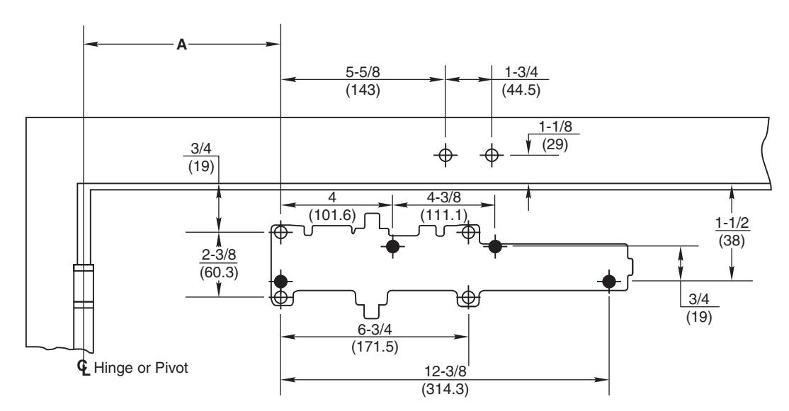
Do Not Scale Drawing
Right Hand Door Shown
Dimensions are in inches (mm).
486 Backplate Mounting Hole Only
| Dimension A | |||
|---|---|---|---|
| Opening | inches | mm | |
| To 100° | 7-5/8 | 194 | |
| 101° to 120° | 6-5/8 | 168 | |
| 121° to 150° | 4-5/8 | 117 | |
| 151° to 180° | 4-1/8 | 105 | |
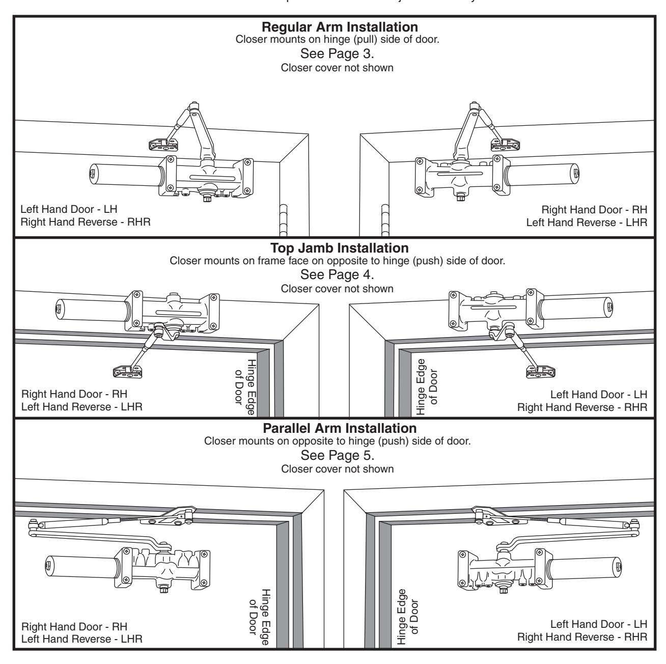
Installation Sequence
- Select angle of opening and use dimensions shown to locate 4 holes on door for closer body or backplate and 2 holes on frame face for arm shoe. For applications that are different from above, a separate template will be required.
- Prepare door and frame for fasteners. See "Preparation for Fasteners", Figure 2, Page 2.
- Mount 486 Backplate ... only if required.
- Install closer with power adjustment nut toward lock edge of door. Valves UP for Right hand door – Valves DOWN for Left hand door.
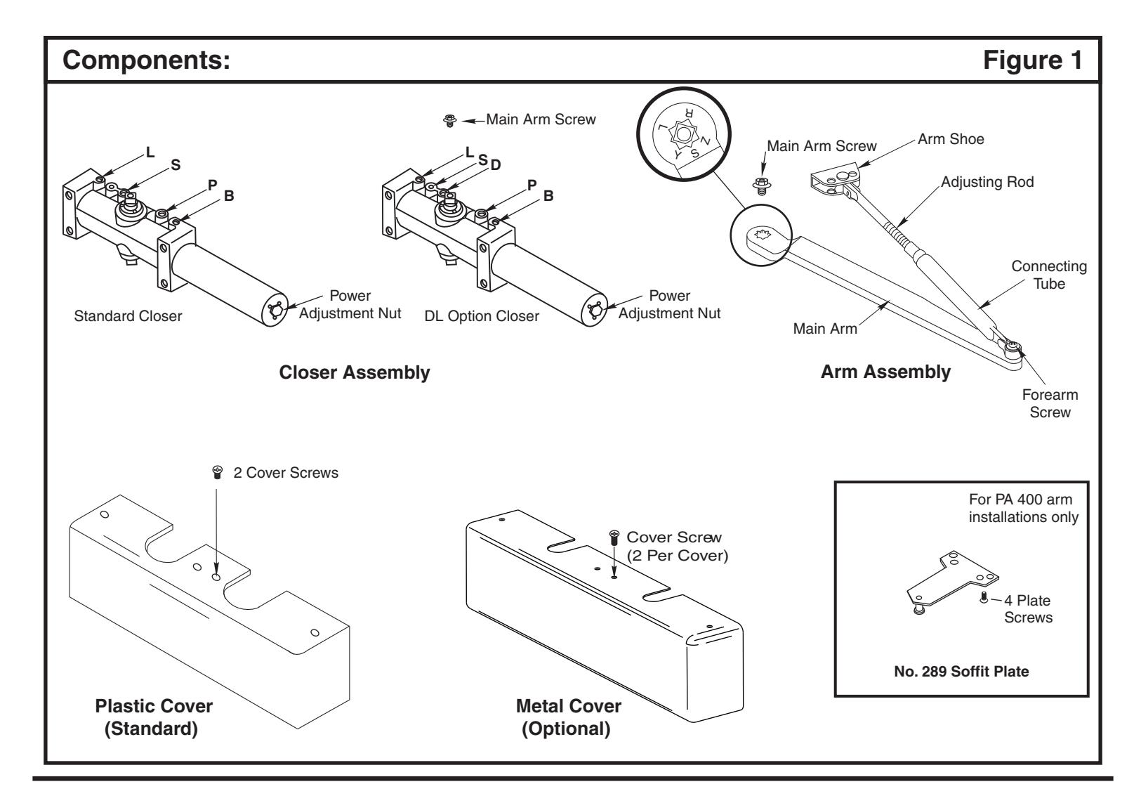
- Remove forearm screw from elbow joint and disassemble arm. See Figure 1. Fasten arm shoe (with rod and tube assembled) to frame face.
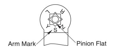
- Mount main arm onto closer pinion shaft, aligning arm mark "S" with pinion flat. Secure with main arm screw.
- Reassemble arm. Adjust forearm length so that it will be perpendicular (at a 90° angle) to the door face when connected to the main arm. Secure with forearm screw.
- · Adjust closer (see Page 6) and install cover.
Page 3 80-9344-1101-010 (06-09)
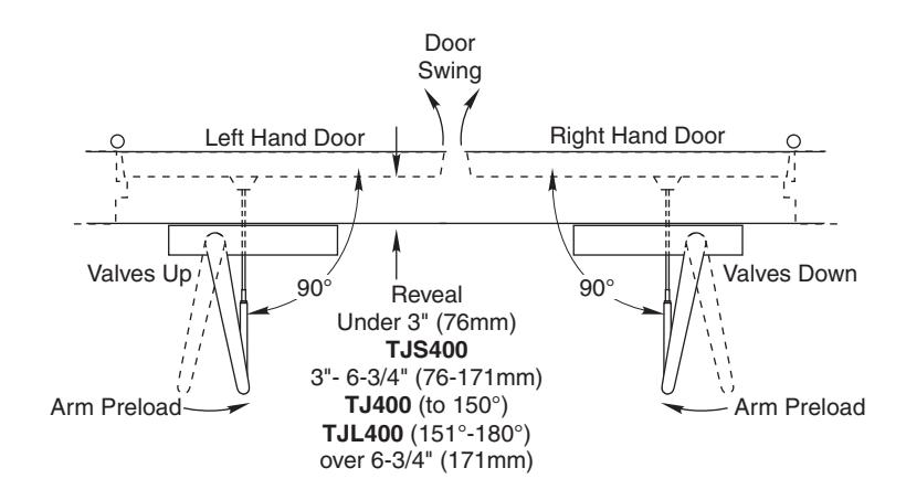
Top Jamb
Template
Installation Sequence
- Select angle of opening and use dimensions shown to locate 4 holes on frame face for closer body or backplate and 2 holes on door for arm shoe. For applications that are different from above, a separate template will be required.
- Prepare door and frame for fasteners. See "Preparation for Fasteners", Figure 2, Page 2.
- Mount 486 Backplate ... only if required.
- Install closer with power adjustment nut toward lock edge of door. Valves UP for Left hand door Valves DOWN for Right hand door.
- Remove forearm screw from elbow joint and disassemble arm. See Figure 1. Fasten arm shoe (with rod and tube assembled) to door.
- Mount main arm onto closer pinion shaft, aligning arm mark "S" with pinion flat. Secure with main arm screw.
- Reassemble arm. Adjust forearm length so that it will be perpendicular (at a 90° angle) to the door face when connected to the main arm. Secure with forearm screw.
- · Adjust closer (see Page 6) and install cover.
151° to 180°
4-1/8
105
Parallel Arm
Template
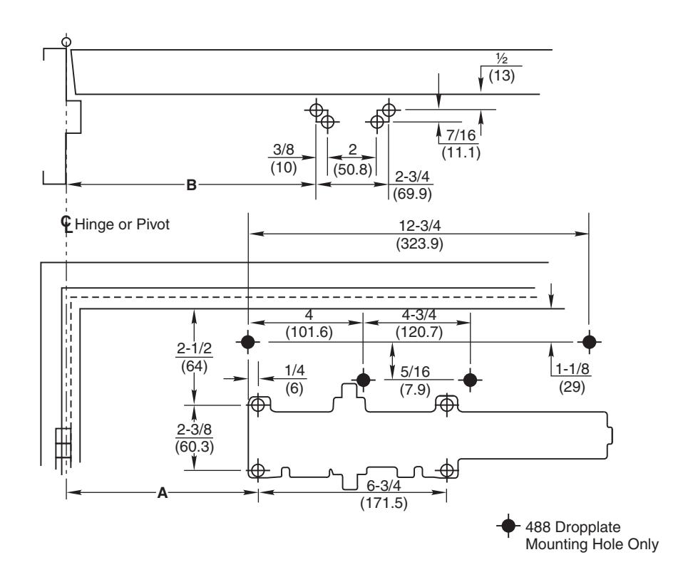

Do Not Scale Drawing
Left Hand Door Shown
Dimensions are in inches (mm).
| Dimension A | Dimension B | |||
|---|---|---|---|---|
| Opening | inches | mm | inches | mm |
| To 100° | 8-3/4 | 222 | 9-1/4 | 235 |
| 101° to 130° | 7-1/4 | 184 | 7-3/4 | 197 |
| 131° to 150° | 6-1/4 | 159 | 6-3/4 | 171 |
| 151° to 180° | 5-1/4 | 133 | 5-3/4 | 146 |
Installation Sequence
- Select angle of opening and use dimensions shown to locate 4 holes on door for closer body and 4 holes on underside of frame for soffit plate. For applications that are different from above, a separate template will be required. or dropplate
- Prepare door and frame for fasteners. See "Preparation for Fasteners", Figure 2, Page 2.
- Mount 488 Dropplate ... only if required.
- Install closer with power adjustment nut toward lock edge of door. Valves for hand door – Valves for hand door. DOWN Left UP Right
- Mount soffit plate to frame. Disassemble arm at forearm-screw (See Figure 1) and attach adjusting rod and connecting tube to soffit plate.
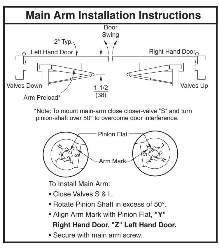
- Install main arm on pinion shaft ...See Main Arm Installation Inst uctions at right. r
- Preload is accomplished by adjusting forearm length so that it will set arm elbow about 1-1/2" (38mm) from the door face when connected to the main arm. Secure with forearm screw. Reassemble arm.
- Connect to main arm. Secure with forearm screw.
- Adjust closer (see Page 6) and install cover.
Unit Adjustment
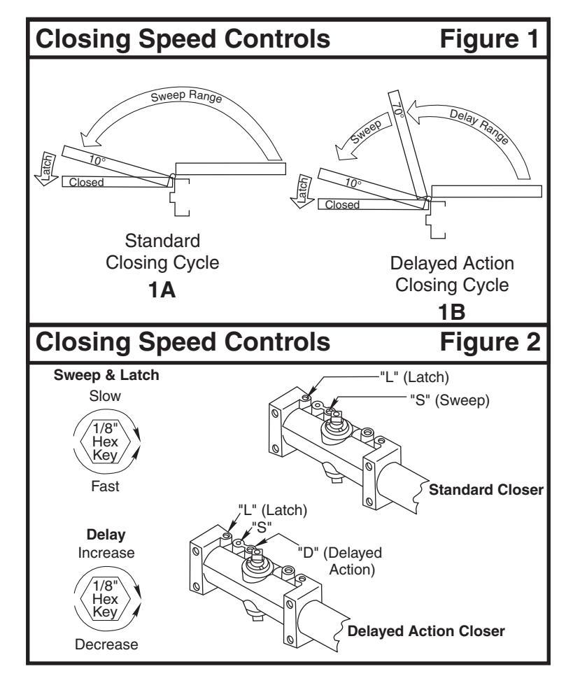
Closing Speed Controls (Figure 1A or 1B and 2.)
- Valve "S" Controls Sweep Range.
- Valve "L" Controls Latch Range.
- Optional Valve "D" Controls Delay Range
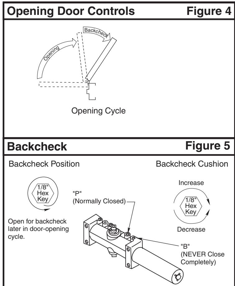
Opening Door Control (Figure 4.)
- Backcheck ("B") valve controls the hydraulic resistance to door opening. NEVER close this valve completely – it is not to provide a positive stop.
- Backcheck position ("P") valve controls the door angle where backcheck cushioning starts. Valve normally closed.
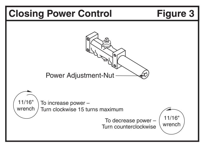
Closing Power Control (Figure 3)
· Adjust as required.