ASSA ABLOY ACCENTRA 250 Series, Low Profile Arm, Non-Hold Open Only Installation Instructions_80-9350-2527-010
Open the original PDF document
View PDFYale <sup>®</sup>
Installation Instructions 80-9350-2527-010 (06-09)
Non Hold Open Models
Narrow Profile Series 250 Series Sized Closers 251(BF) Series Multi-Sized Closers
An incorrectly installed or improperly adjusted door closer can cause properly damage or personal injury. These instructions should be followed to avoid the possibility of misapplication or misadjustment.
Sized (Sizes 4,5,& 6)
254(BC)
251
255(BC) 256(BC)
(Sizes 1 thru 4) 251BF
Multi-Sized
(Sizes 3 thru 6)
The Habitat for Humanity®
"BC" suffix (Backcheck) is an optional feature for sized closers but is standard with Multi-Sized closers. See Page 3 for an explanation of the Backcheck feature.
"DL" suffix (Delayed Action) is an optional feature.
A separate instruction showing valve locations and adjustment procedures will be packed with these instructions.
NOTE: For special applications a separate door and frame preparation template is packed with these instructions Use this instruction sheet for installation sequence and closer adjustments only
- It is recommended that the door on which the door closer will be installed be hung on ball bearing hinges. Door must swing freely
- A separate door stop, supplied by others, is recommended to prevent damage to the door closer, closer arm, or to the door, frame or adjacent walls.
- Door and Frame must be properly reinforced, or use of special fasteners employed, to prevent the mounting screw from pulling out.
- · All dimensions are given in inches with corresponding metric dimensions (mm) in parenthesis.
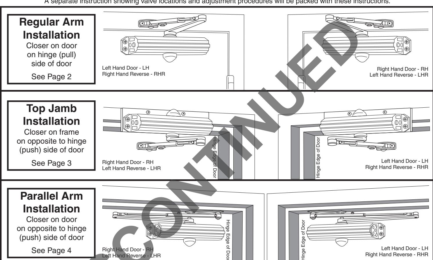
Regular Arm Installation
Installation Sequence
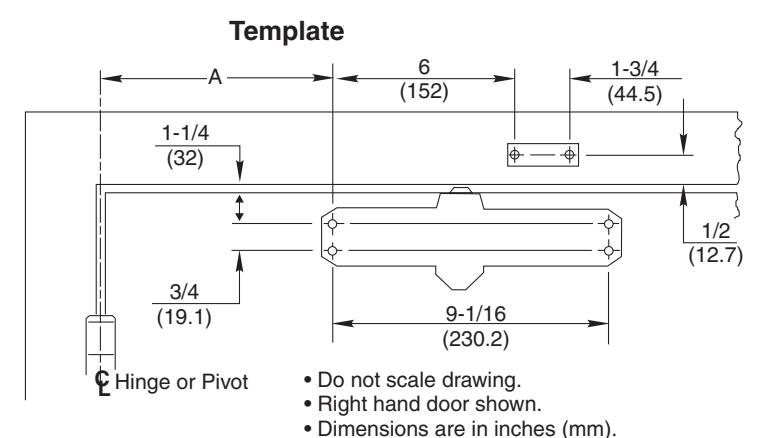
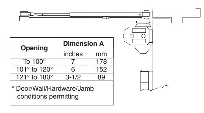
- Select door opening angle using template above. Mark 4 holes on door for closer and 2 holes on frame for arm shoe.
- Prepare door and frame for fasteners See "Preparation for Fasteners" below.
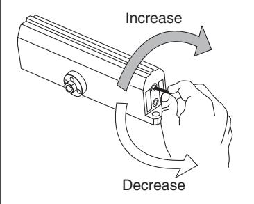
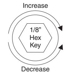
- ! 251 or 251BF Models Only. Set closing power using "Power Adjustment Chart" below right.
- Install closer with "S" and "L" adjustment valves toward hinge edge of door.
- Mount arm shoe to frame face.
- Install main arm onto closer pinion shaft, indexing main arm mark "S" with pinion flat as shown at right. Fasten with arm screw.
| Preparation for Fasteners | |||||||
|---|---|---|---|---|---|---|---|
| Fasteners D | oor or Frai | me Drill-Sizes | |||||
| Self-Drilling Screw | Aluminum or Metal | No drill required | |||||
| Standard | Wood | 3/16" (4.30 mm) | |||||
| 1/4" - 20 machine screw | Metal |
Drill: #7 (0.201" dia.)
Tap: 1/4" - 20 |
|||||
| Sleeve nuts and bolts |
Hollow
Metal |
9/32" (7 mm) through;
3/8" (9.5 mm) door face opposite to closer |
|||||
| Optional | Aluminum or Wood | 3/8" (9.5 mm) through | |||||
| Through-bolts and grommet-nuts | All |
9/32" (7 mm);
3/8" (9.5 mm) dia. x 3/8" (9.5 mm) deep on door opposite to closer |
|||||
Side Elevation
- Open door to allow connecting rod to be inserted into arm slide. Insert rod and close door. Preload main arm by rotating away from hinge until forearm is perpendicular (at 90° angle) to door. Secure with forearm screw.
- Screw pinion cap onto pinion shaft by hand or with a Phillips screw driver -DO NOT OVER TIGHTEN.
- Adjust closer.
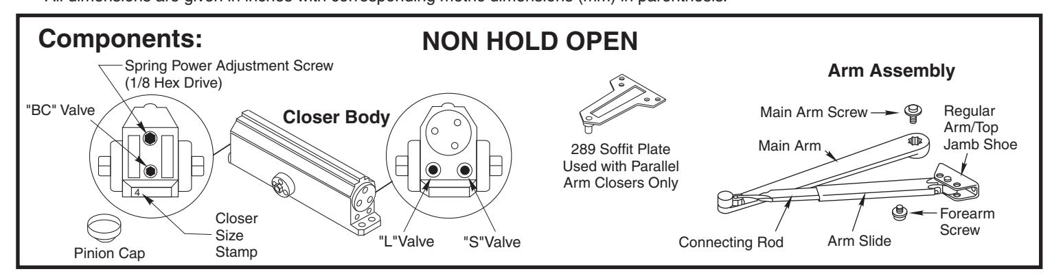
Door Closer Adjustment
| Power Adjustment Chart | ||||||||||
|---|---|---|---|---|---|---|---|---|---|---|
| Ä | TYPE OF INSTALLATION * | 4 | MAXIM | MAXIMUM DOOR SIZE | ||||||
| DOOR |
34"
(0.85 m) |
36"
(0.9 m) |
40"
(1 m) |
44"
(1.1 m) |
48"
(1.2 m) |
|||||
| INTERIOR | REGULAR ARM TOP JAMB |
FULL 360° TURNS
OF POWER ADJUSTMENT SHAFT |
1 | 1 | 2 | 3 | 3 | |||
| BF | PARALLEL ARM | 2 | 2 | 3 | 4 | 5 | ||||
| 251 | EXTERIOR | REGULAR ARM TOP JAMB | 5 | 6 | 8 |
NOT
RECOMMENDE USE 251 |
||||
| l | PARALLEL ARM | 8 | 9 | 12 | ||||||
| INTERIOR | REGULAR ARM TOP JAMB |
FULL 360° TURNS
POWER ADJUSTMENT SHAFT |
2 | 4 | 6 | 9 | 11 | |||
| 251 | :| E | PARALLEL ARM | 3 | 5 | 7 | 10 | 13 | |||
| 2 | 'n | EXTERIOR |
REGULAR ARM
TOP JAMB |
3 | 5 | 7 | 10 | 13 | ||
| EXT | PARALLEL ARM | P | 5 | 7 | 10 | 14 | 16 | |||
| 1 | *18 -360° TURNS MAXIMUM AVAILABLE | |||||||||
Top Jamb Installation Using 587 Dropplate
Template A 7 (178) 1/2 (13) (38.1) (101.6) 7/8 (22) Do not scale drawing. • Left hand door shown. • Dimensions are in inches (mm).
Opening Dimension A inches mm To 100° 8-1/2 216 101° to 120° 7 177.8 121° to 180° 4-1/2 114 * Door/Wall/Hardware/Jamb conditions permitting
Installation Sequence
- Select door opening angle using template above. Mark 4 holes on frame face for Dropplate and 2 holes on door for arm shoe.
- Prepare door and frame for fasteners. See "Preparation for Fasteners" at bottom of Page 2.
- ! 251 or 251BF Models Only. Set closing power using "Power Adjustment Chart" at bottom of Page 2.
- . Mount drop plate to frame.
- Install closer to drop plate with "S" and "L" adjustment valves toward hinge edge of door.
- . Mount arm shoe to door.
- Install main arm onto closer pinion shaft, indexing main arm mark "S" with pinion flat as shown at right. Fasten with arm screw.
- Open door to allow connecting rod to be inserted into arm slide. Insert rod and close door. Preload main arm by rotating away from hinge until forearm is perpendicular (at 90° angle) to door. Secure with forearm screw.
- Screw pinion cap onto pinion shaft by hand or with a Phillips screw driver - DO NOT OVER TIGHTEN.
- · Adjust closer.
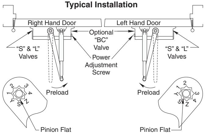
Typical Installation
Door Closer Adjustment (Continued)
"DA" suffix (Delayed Action) is an optional feature. A separate instruction will be packed with these instructions showing valve locations and
A separate instruction will be packed with these instructions showing valve locations and adjustment procedures.
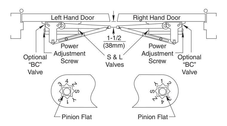
Unit Adjustment
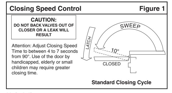
Closing Speed Controls (Figure 1)
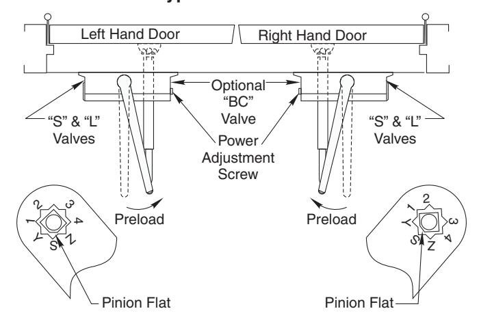
- Valve "S" controls sweep range.
- Valve "L" controls latch range.
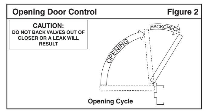
Opening Door Control
Backcheck ("BC") valve controls the hydraulic resistance to door opening in backcheck range. NEVER close this valve completely it is not to provide a positive stop.
Parallel Arm Installation
Template
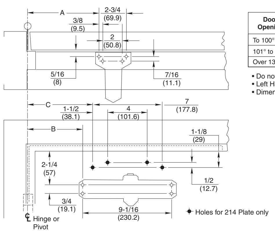
| Door | Dimension A | Dimension B | Dimension C | |||
|---|---|---|---|---|---|---|
| Opening | Inches | mm | Inches | mm | Inches | mm |
| To 100° | 9-1/4 | 235 | 7-5/8 | 194 | 8-5/8 | 219 |
| 101° to 130° | 7-3/4 | 197 | 6-1/8 | 156 | 7-1/8 | 181 |
| Over 131° | 5-3/4 | 146 | 4-1/8 | 105 | 5-1/8 | 130 |
- Do not scale drawing
- Left Hand shown
- Dimensions are in inches (mm)
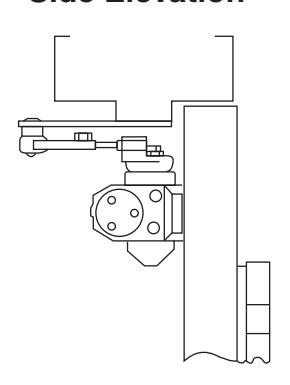
Side Elevation
Installation Sequence
- Select door opening angle using template above. Mark 4 holes on door for closer or 214 dropplate and 4 holes on frame for soffit plate.
- Prepare door and frame for fasteners. See "Preparation for Fasteners" bottom of Page 2.
- 251 or 251BF Models Only. Set closing power using "Power Adjustment Chart" at bottom of Page 2.
- Mount 214 dropplate ... only if required.
- Install closer with "S" and "L" adjustment valves toward lock edge of door.
- Mount soffit plate to frame.
- Install main arm onto closer pinion shaft. Rotate pinion 45° toward hinge edge of door to align main arm letter "3" (right hand) or "2" (left hand) with pinion flat. Fasten with arm screw.
- Fasten forearm to soffit plate. Adjust forearm length to set arm elbow about 1-1/2" (38mm) from door when connected to main arm. Tighten forearm screw.
- Screw pinion cap onto pinion shaft by hand or with a Phillips screw driver - DO NOT OVER TIGHTEN.
- Adjust closer. See Closer Adjustments on Pages 2 and 3.
Typical Installation
Yale
An ASSA ABLOY Group brand
3000 Highway 74 East • Monroe, NC 28112 Tel: (800)-438-1951 • Fax: (800)-338-0965 www.yalecommercial.com