ASSA ABLOY ACCENTRA 2170(F) Wide Stile SVR 790 Floor Strike Wood or Composite Doors and H.M. Frame_7427-1010
Open the original PDF document
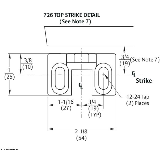
View PDFReinforcement for 726 Strike (See Note 6)
NOTES:
- 1. Do not scale drawing.
- 2. Dimensions are in inches (mm).
- 3. LHR door shown. Preparation is typical for both door hands.
- 4. Minimum door stile width: 4-1/2 (114).
- 5. Prepare mounting holes when installing the device.
- 6. Unreinforced frames require blind rivet nuts (by others) to mount the strike.
- 7. Thi s hole MUST be field located using physical part as template, after installation is complete and device is fully operational.
- 8. For outside trim preparation see appropriate trim template.
- 9. Provide adequate structural support to maintain door integrity after device installation with power tools, door use, or abuse.
- 10. Device mount to hinge stile (not shown) requires hole location and preparation during device installation. Door structural requirements to support the device cases are similar for both door stiles.
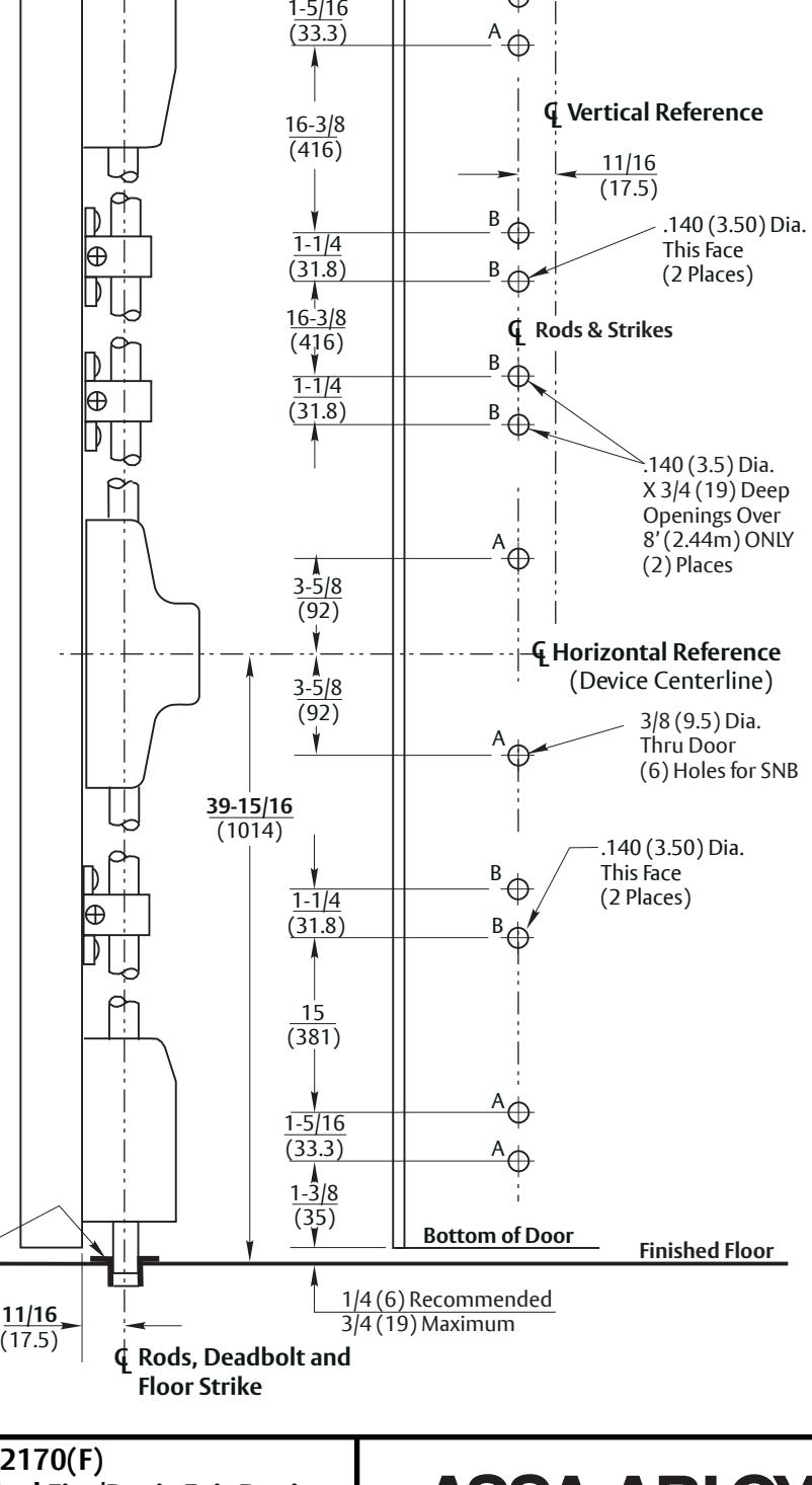
- 11. Bottom bolt should retract to 1/8 (3.2) above floor strike. Floor coverings in the door path must be laid accordingly.
- 12.Wood screws #14 x 1-1/2" (by others) permitted for solid core wood doors if pilot holes are used for installation, when door label allows its use.
2-3/4 (70)
A
Inside Face of Door
CLDoor
See Note 10
2-1/4 (57)
Lock Edge
RESPONSIBILITY
DOOR AND FRAME MANUFACTURERS ARE RESPONSIBLE FOR PROVIDING ADEQUATE CONSTRUCTION OR REINFORCEMENTS FOR PROPER INSTALLATION OF HARDWARE SHOWN. ALL ARCHITECTURAL BUILDERS HARDWARE MUST BE INSTALLED ON PROPERLY REINFORCED DOORS AND FRAMES, REGARDLESS OF TYPE,
Surface Vertical Rod Fire/Panic Exit Device
5/8 (16) Dia. X 3/4 (19) Deep for 790 Strike
Application For Approved Wood or Composite Doors and H.M. Frame
MATERIAL, OR METHOD OF CONSTRUCTION. Contact us for support at 1-855-557-5078.
7427-1010 DATE SUPERSEDES DO NOT SCALE DRAWING TEMPLATE NUMBER 04/10 12-23