ASSA ABLOY ACCENTRA 2116 Alarm Kit for 2100 Series (Discontinued August 2012) Instructions_80-9420-2116-000
Open the original PDF document
View PDFTROUBLESHOOTING
Problem
Solution
· Alarm will not sound
- Battery is not connected.
- Battery needs replacing
- Alarm in not ARMED. Turn key clockwise.
- Alarm sounds when keyswitch is activated.
-
Touchbar Switch is out of position. Verify that switch opens when Touchbar is depressed, and closes when Touchbar is released.
- Position switch lever as necessary.
- Tamper Switch is not closing when Alarm Cover is installed.
- Touchbar is bound and not returning, Check by pulling on Touchbar and arming.
- · White connector not connected.
-
Alarm chirps every 10 seconds. Low battery indicator, replace battery.
- ARMED indicator LED, wrong color.
-
Change position of DS-5 Dip Switch.
- "OFF" for RED ARMED indicator.
- "ON" for GREEN ARMED indicator.
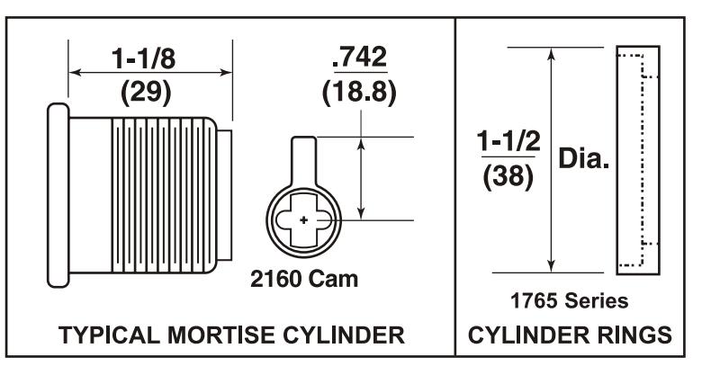
Cylinders and Rings
Use standard 1-1/8" mortise cylinder with 2160 cam. Yale number 2153 x 1-1/8" cylinder.
Cylinder Ring is not required.
Cylinder Rings are required for use with cylinders longer than 1-1/8".
Yale* is a registered trademark of Yale Security Inc. Other product brand names may be trademarks or registered trademarks of their respective owners and are mentioned for reference purposes only. These materials are protected under US copyright laws. All contents current at time of publication. Yale Security Inc. reserves the right to change availability of any item in this manual, design, construction, and/or it's material.
Copyrighto 2003, 2006 Yale Security Inc. all rights reserved.
Yale ®
Commercial Locks & Hardware
100 Yale Avenue Lenoir City, TN 37771-3226
(865) 986-7511 (Direct) (865) 986-8630 (Fax)
WEbsite: www.yalecommercial.com

2116 ALARM KIT FOR 2100 SERIES EXIT DEVICE
INSTALLATION INSTRUCTIONS
80-9420-2116-000 Rev.C

Alarm Label
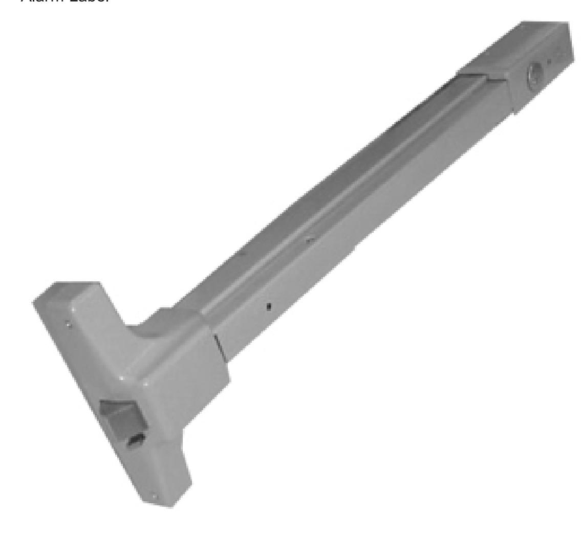
2116 Alarm Retrofit Kit
Available for field retrofit of all devices except Surface Vertical Rod
EXIT ALARM INSTRUCTIONS
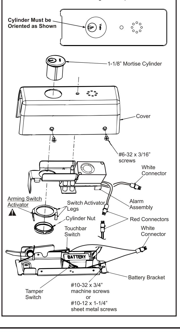
STEP 1 - Alarm Assembly
- 1. Remove alarm cover and verify Dip Switch settings per Page 3.
- 2. Connect battery.
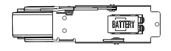
- 3. Insert Cylinder into Cover.
Note: Cylinder keyway horizontal and toward the open side of Cover.
- 4. Insert Alarm Assembly onto the Cover as shown.
- 5. Install Arming Switch Activator over Cylinder so that the Activator legs are on each side of the toggle switch. See board detail on next page. A
- 6. Secure parts with Cylinder Nut, making sure Arming Switch Activator rotates freely. Check that rotating the key causes the Activator to trip switch in both directions. Bend Activator legs as required.
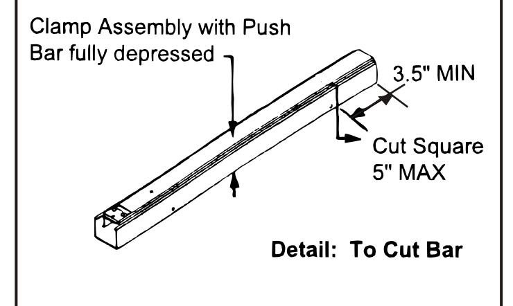
STEP 2 - Size Device
- 1. For New Installation Size touchbar assembly per installation instructions supplied with device, except cut 5" shorter to allow room for alarm assembly
- 2. For Existing Installations Cut 5" off existing touchbar.
Note: Clamp Assembly with Bar fully depressed when cutting Figure 1. Verify there is 3-1/2" or more between the bar pin and cut line to avoid damaging the bar assembly.
STEP 3 - Install Touchbar Assembly
- 1. For New Installation, install latch head.
- 2. Insert Touchbar assembly into latch head.
- 3. Use Battery Bracket to mark mounting holes. Drill and tap for (3) #10-24 screws.
- 4. Insert battery bracket into end of touchbar assembly and mount with (3) #10-24 screws.
- 5. Connect red and white connectors from Alarm Board to Battery Bracket and install cover with (4) #6-32 screws.
- 6. Install Alarm Label on Touchbar or on door above
Note: Make sure wires do not interfere with switch operation.
ALARM FUNCTION AS SHIPPED
- 1) Upon arming, LED will flash AMBER and the device will allow egress without triggering alarm for 20 seconds.
- 2) After 20 seconds, alarm will chirp one time and the device will be ARMED . The LED will flash RED every 30 seconds, indicating the device is ARMED .
- 3) After Arming, unauthorized egress will result in an alarm sound that will stop only when the device is RE-ARMED by key or remote.
- 4) Low Battery Indicator Alarm will chirp every 10 seconds, indicating battery needs to be replaced.
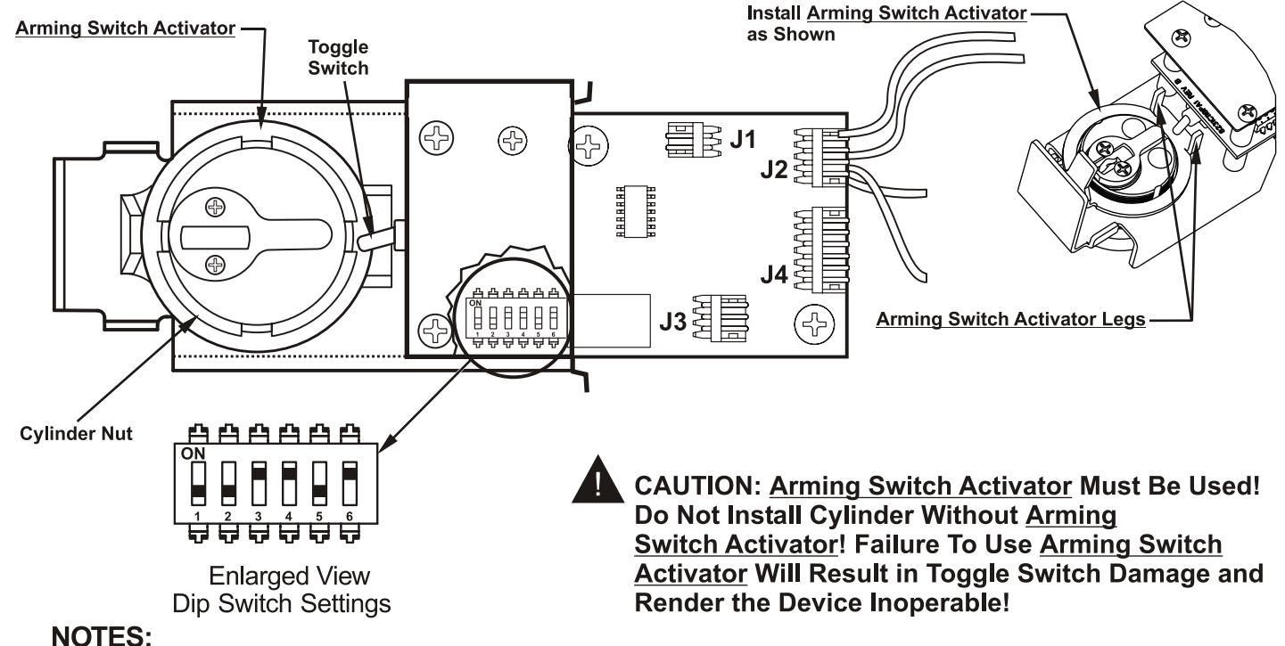
- Alarm PC Board has Dip Switches DS-1, 2, 3, 4, and 5 factory preset per Tables 1, 2, and 3 shown below.
- Dip Switch DS-6 is for "hard wire" configurations and setting does not affect stand-alone battery operation.
| REX and Passage Time Delay When the device is initially ARMED by key, the LED will flash AMBER and allow egress for a time defined in Table 1. | TABLE 1 | ||
|---|---|---|---|
| DS-1 | DS-2 | Timer Delay | |
| *Off | *Off | 7 Seconds | |
| Off | On | 10 Seconds | |
| On | Off | 15 Seconds | |
| On | On | 20 Seconds | |
| Automatic Alarm Reset | TABLE 2 | ||
| The alarm can be set so that it will reset itself after a violation has occurred per Table 2. If the device automatically resets, the indicator light will flash GREEN every 30 seconds instead of RED to indicate a violation has occurred. | DS-3 | DS-4 | Reset Time |
| Off | Off | 2 Minutes | |
| Off | On | 5 Minutes | |
| On | Off | 10 Minutes | |
| *On | *On | No Auto Reset | |
| Armed and Violation LED Color Selection | TABLE 3 | ||
| Device is shipped standard, per Table 3, so that RED LED flashes every 30 seconds when device is ARMED , and flashes GREEN every 30 seconds under auto reset, when door has been violated. | DS-5 |
Armed
LED Color |
Armed Violation
LED Color |
| *Off | Red | Green | |
| On | Green | Red | |