ASSA ABLOY ACCENTRA 1500 Series 1530(F) Wide Stile Mortise ANSI A115.1 Strike Optional SNB Wood_7415-1030
Open the original PDF document
View PDF
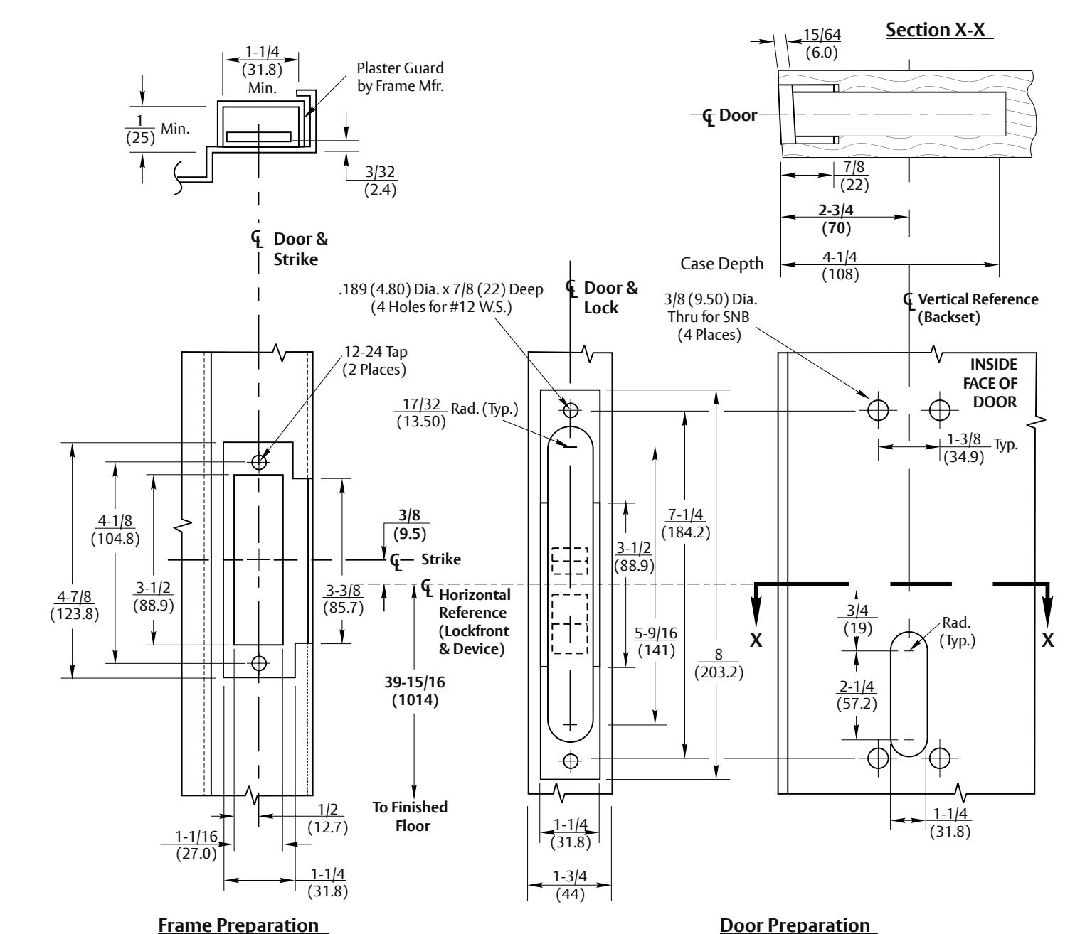
Frame Preparation
NOTES:
- 1. Do not scale drawing.
- 2. Dimensions are in inches (mm).
- 3. LHR door shown. Preparation is typical for both door hands.
- 4. Minimum door stile width 4-1/2(114).
- 5. Prepare mounting holes when installing the device.
- 6. Provide adequate structural support to maintain door integrity after device installation with power tools, door use, or abuse.
- 7. Device mount to hinge stile (not shown) requires hole location and preparation during device installation. Door structural requirements to support the device cases are similar for both door stiles.
- 8. For outside trim preparation see appropriate trim template.
- 9. Unless otherwise specified, preparation and dimensional tolerances must conform to ANSI A115.1 (frame) and A115.W1 (door).
- 10. Dimensions given about a centerline are symmetrical.
- 11.Wood screws #14x1/12", (by others) permitted in solid core wood doors if pilot holes are used for installation, when door label allows
- 12. For electrical device suffixes "SAFE" or "SECURE" also see template 7477-0001.
- 13. Latchbolt centerline is 23/32 (18.2) below and Aux. Blot centerline is 3/16 (4.8) above centerline of Lockfront.
RESPONSIBILITY
DOOR AND FRAME MANUFACTURERS ARE RESPONSIBLE FOR PROVIDING ADEQUATE CONSTRUCTION OR REINFORCEMENTS FOR PROPER INSTALLATION OF HARDWARE SHOWN ALL ARCHITECTURAL BUILDERS HARDWARE MUST BE INSTALLED ON PROPERLY REINFORCED DOORS AND FRAMES REGARDLESS OF TYPE MATERIAL, OR METHOD OF CONSTRUCTION.
1530 and 1530F Mortise Exit Devices with ANSI A115.1 Strike & Optional SNB
Application to Wood or Composite Door and H.M. Frame
Contact us for support at 1-855-557-5078.
ASSA ABLOY
SUPERSEDES DO NOT SCALE DRAWING TEMPLATE NUMBER 7415-1030 12 - 23