ASSA ABLOY ACCENTRA 1101 Series, Non-Hold Open (Units Shipped Prior to December 2012) Installation_UA304-HHO-1101
Open the original PDF document
View PDFDOOR CLOSER
INSTALLATION INSTRUCTIONS
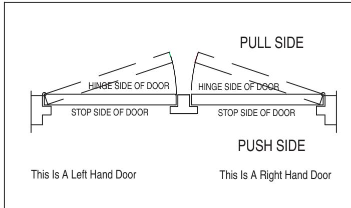
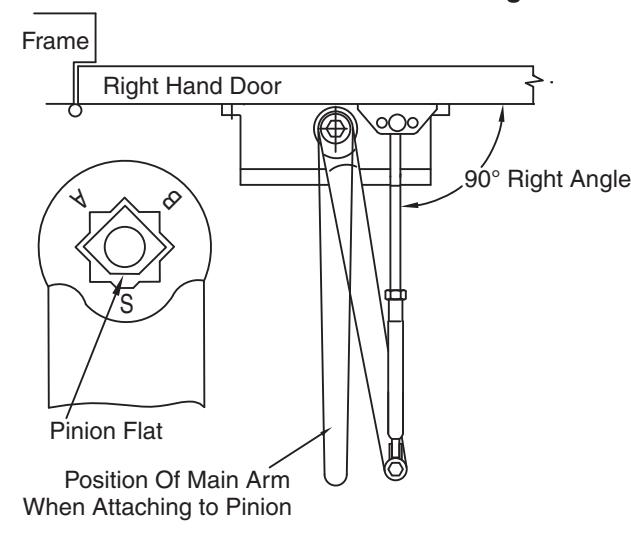
Chart To Determine Hand Of Door
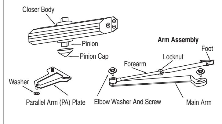
Components
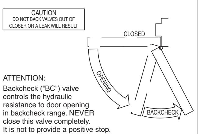
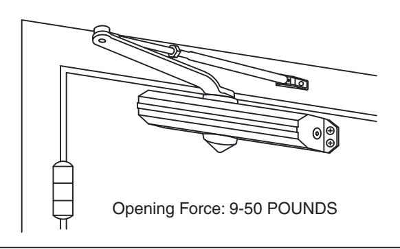
Control Function
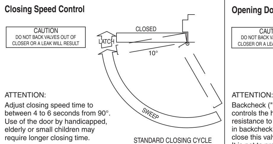
Opening Door Control
Final Adjustment And Regulating Procedures *
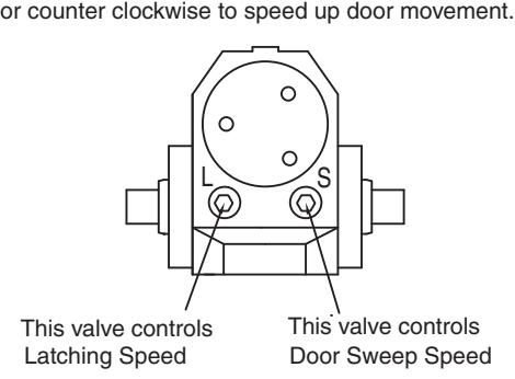
Regulating Door Speed And Latching Speed
Turn speed regulating valve clockwise to slow down
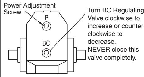
Regulating BC Power Regulating Spring Power
Turn this screw clockwise to increase or counter clockwise to decrease.
*Regulating Spring Power for Multi sized closer only - not valid for fixed sized closers.
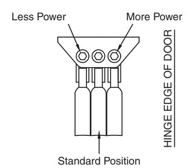
Adjusting Foot For Closing Power
Move foot pivot to hole as illustrated below
1 UA304-NHO-1101 Rev A 9/10
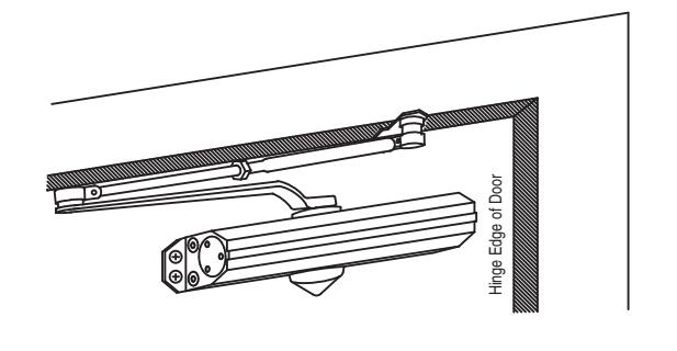
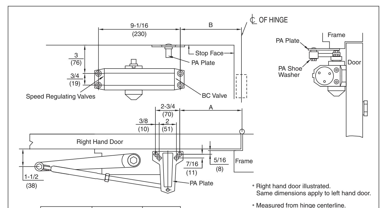
REGULAR ARM INSTALLATION
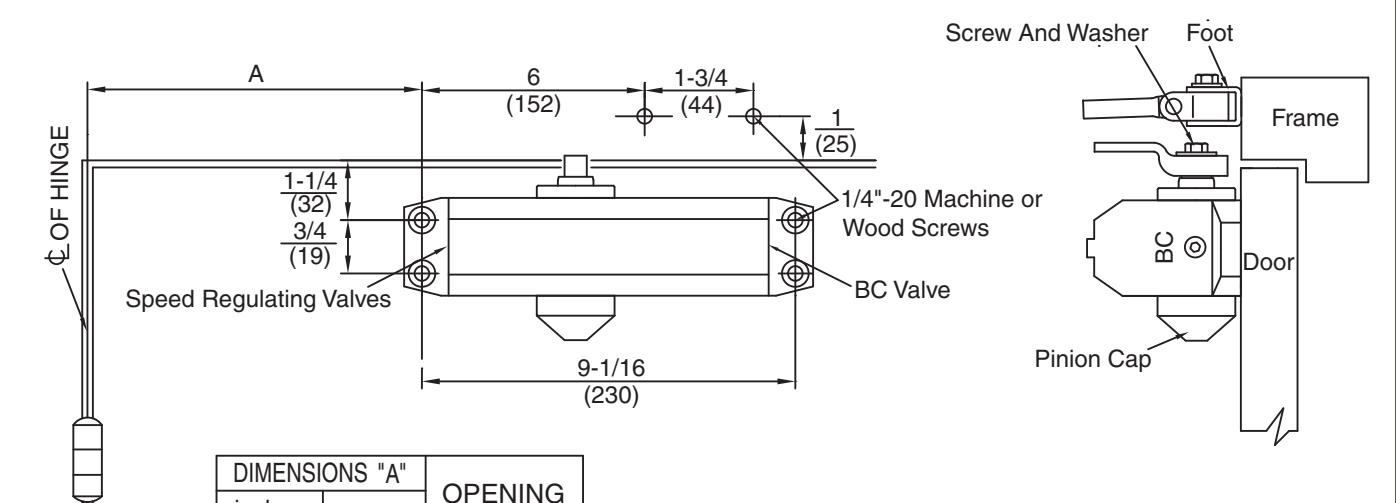
DIMENSIONS "A" inches mm OPENING 7 178 TO 100° 6 152 101° TO 120° 3-1/2 89 *121° TO 180°
- Right hand door illustrated. Same dimensions apply to left hand door.
- Measured from hinge centerline. Dimensions are in inches (mm).
- · Do not scale drawing.
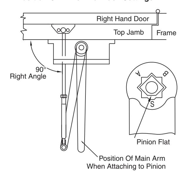
Position Of Arms And Index Settings
INSTALLATION INSTRUCTIONS
- Select degree of door opening. Use dimensions shown in chart to mark location of attaching screws on door and frame. Prepare holes.
- 2. Assemble main arm to closer.
- Attach closer to door with speed regulating valves toward hinge.
- 4. Attach the foot of the forearm to frame.
- Adjust length of forearm to position forearm at right angle to frame. When connected to main arm at elbow, use washer and screw provided to secure pivot connection. Tighten locknut on forearm.
- 6. Snap pinion cap over pinion at bottom of closer.
- 7. Adjust closer.
| ★★ Power Adjustment Chart | |||||||
|---|---|---|---|---|---|---|---|
| Æ | TYPE OF INSTALLATION | * | MAXIMUM DOOR SIZE | ||||
| DOOR |
34"
0.85M |
36"
0.90M |
40"
1.00M |
44"
1.10M |
48"
1.20M |
||
| ROR |
REGULAR ARM
TOP JAMB |
360° TURNS OF
ER ADJUSTMENT :T |
2 | 4 | 6 | 9 | 11 |
| INTERIOR | PARALLEL ARM | 3 | 5 | 7 | 10 | 13 | |
| EXTERIOR | REGULAR ARM TOP JAMB | 4 | 6 | 8 | 11 | 14 | |
| EXTE | PARALLEL ARM |
FULL 360
POWER SHAFT |
6 | 8 | 10 | 15 | 17 |
| * 18-360° TURNS MAXIMUM AVAILABLE | |||||||
** Regulating Spring Power for Multi sized closer only - not valid for fixed sized closers.
* Door/Wall/Hardware/Jamb conditions permitting
TOP JAMB INSTALLATION
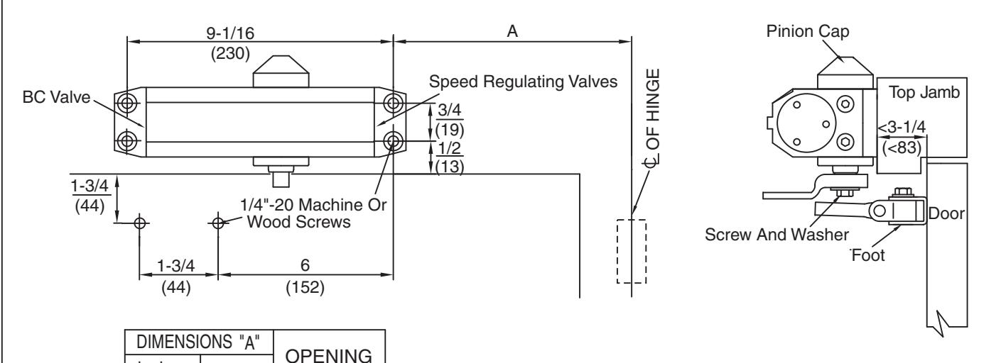
| DIMENSIONS | "A" | |||
|---|---|---|---|---|
| inches | mm | OPENING | ||
| 7 | 178 | TO 100° | ||
| 6 | 152 | 101° TO 120° | ||
| 3-1/2 | 89 |
121° TO 180°
* |
||
* Door/Wall/Hardware/Jamb conditions permitting
- Right hand door illustrated. Same dimensions apply to left hand door.
- Dimensions are in inches (mm). Measured from hinge centerline.
- Do not scale drawing.
Position Of Arms And Index Settings
INSTALLATION INSTRUCTIONS
- 1. Select degree of door opening. Use dimensions shown in chart to mark location of attaching screws on door and frame. Prepare holes.
- 2. Assemble main arm to closer.
- 3. Attach closer to frame with speed regulating valves toward hinge.
- 4. Attach the foot of the forearm to door.
- 5. Adjust length of forearm to position forearm at right angle to frame. When connected to main arm at elbow, use washer and screw provided to secure pivot connection. Tighten locknut on forearm.
- 6. Snap pinion cap over pinion at bottom of closer.
- 7. Adjust closer.

Before installation, adjust the spring power as recommended on chart. DO NOT exceed the maximum number of turns.
Spring power is set at 0 turns from the factory.
Regulating Spring Power for Multi sized closer only - not valid for fixed sized closers.
3 UA304-NHO-1101 Rev A 9/10
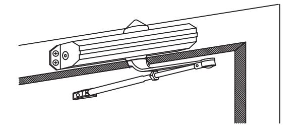
PARALLEL ARM INSTALLATION
| DIMENSIONS "A" | DIMENSI | ONS "B" | ODENINO | |
| inches | mm | inches | mm | OPENING |
| 9-1/4 | 235 | 7-5/8 | 194 | TO 100° |
| 7-3/4 | 197 | 6-1/8 | 156 | 101° TO 130° |
| 5-3/4 | 146 | 4-1/8 | 105 | OVER 131° |

Select degree of door opening. Use dimensions shown in chart to mark location of attaching screws on door and frame. Prepare holes.
Dimensions are in inches (mm).
Attach closer to door with speed regulating valves away from hinge.
· Do not scale drawing.
- 3. Attach PA plate to top frame as shown.
- 4. Remove foot from forearm and discard.
-
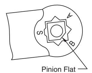
5. Install arm on pinion shaft. Rotate pinion 45° toward hinge edge of door to align main arm.
- "B" (right hand door) or
- "A" (left hand door)
Fasten with arm screw.
- Fasten forearm to PA plate using screw removed from foot in Step 4 and PA shoe washer included in screw pack.
- Adjust forearm length to set arm elbow about 1-1/2" (38mm) from door. When connected to main arm, use washer and screw provided to secure pivot connection. Tighten locknut.
- 8. Snap pinion cap over spindle at bottom of closer.
- 9. Adjust closer.
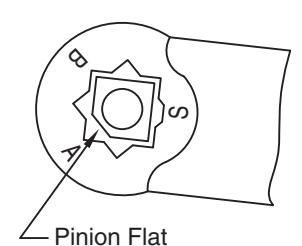

For Right Hand Door