AD8600, MD8600, 12-MD8600, NB-MD8600, NB-12-MD8600 CVR Exit Device Installation Instructions
Open the original PDF document
View PDFInstructions for Installing AD-8600, MD-8600 & 12-MD-8600 Concealed Vertical Rod Exit Devices
For additional information, contact SARGENT at 1-800-727-5477
Verify the correct exit device is being installed on the correct door. Function, finish and size should all be verified. Note: Before removing door from hinges determine the gap between top of door and frame. Determine smallest gap between bottom of door or threshold and high point of floor as door swings. This information is needed for step #7. Remove door from the frame.
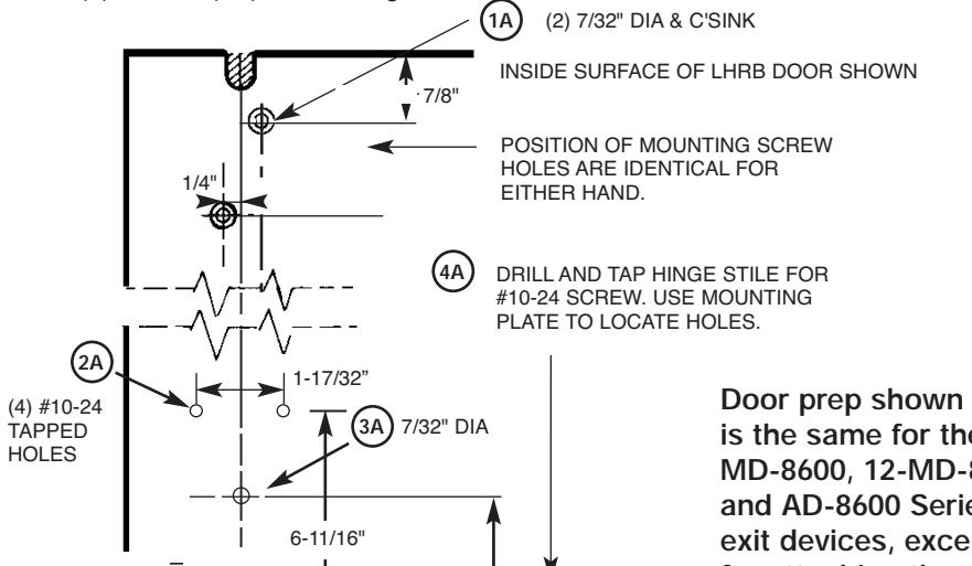
1) Drill, tap & c'sink the door per template, except for the (2) #10-24 (4A) on the hinge side.
4-1/2"
DRILL AND CUTOUT THIS SIDE OF DOOR
DRILL & C'SINK FOR #10 SCREWS 2 PLACES
HINGE STILE
USED WITH AD PREFIX)
is the same for the MD-8600, 12-MD-8600 and AD-8600 Series exit devices, except for attaching the bottom plate. 12- and MD- is shown separately below.
Note: If 100 Series auxiliary control is being used, door must be prepped for Aux Control prior to installing device on to the door. Aux Control can be installed after exit device is installed. See appropriate instructions.
View of door bottom for MD-8600 & 12-MD-8600
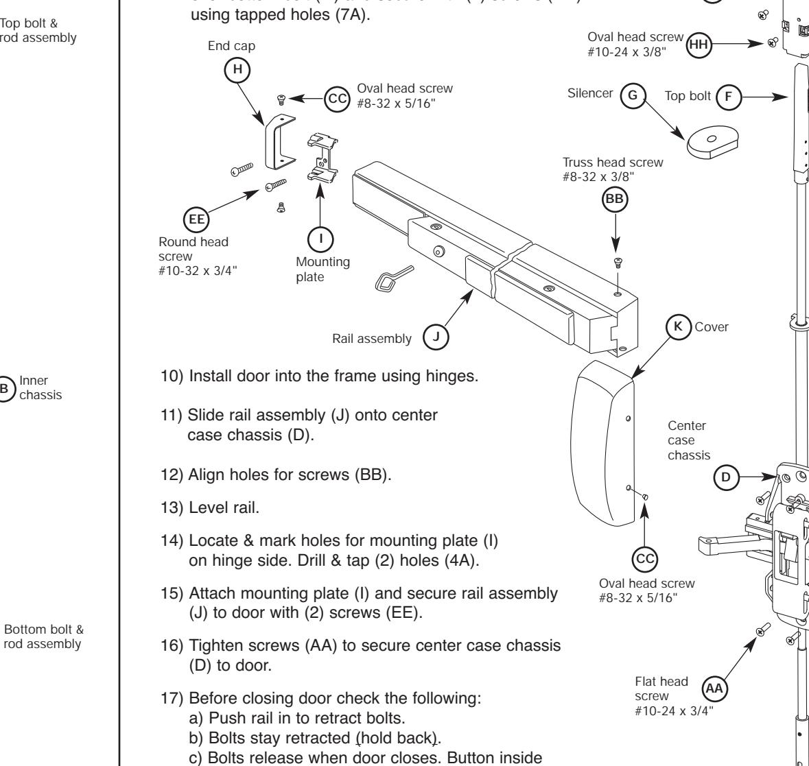
LEFT HAND REVERSE RIGHT HAND REVERSE THIS EXIT DEVICE IS HANDED CHECK HAND OF DEVICE AGAINST APPLICATION OUTSIDE
1/4"
2 3/4" BACKSET
FINISHED FLOOR
5/8" GAP
36-3/4" UNLESS OTHERWISE SPECIFIED
41" STD. HGT.
INSIDE
BEVEL
Information for Cutting Rails Rail Sizes Door Widths Max Min E 32" 24" F 36" 33" J 42" 37" G 48" 43"
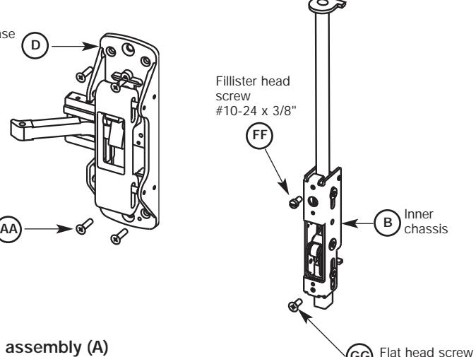
- 2) Screw top bolt & rod assembly (A) and bottom bolt & rod assembly (C) into inner chassis (B).
- 3) Slide complete assembly into top of door.
- 4) Attach inner chassis (B) to door with screw (GG) using hole (5A).
- 5) Then secure with screw (FF) using hole (3A).
Note: If 700 Series ET Controls is being used, it must be installed at this point, prior to step 6. See appropriate instructions.
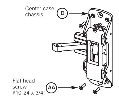
6) Position chassis (D) over fillister head screw and attach to door with (4) screws (AA) using holes (2A). Do not tighten yet.
Note: Rods must be retracted while adjusting bolt projection. Use Chassis (D) to retract top bolt & rod assy (A) & bottom bolt & rod assy (C).
-
7A)
Adjusting the top bolt & rod assembly (A)
- 1) 1/8" gap or less between door top and frame. Rotate bolt to make even with top of the door.
- 2) 1/8"gap or greater. Bolt to extend above door equal to gap minus an 1/8".
-
7B)
Adjusting the bottom bolt & rod assembly (C)
- 1) 1/8" gap or less between door bottom & high point. Rotate bolt to make even with bottom of door.
- 2) 1/8"gap or greater. Bolt to extend below door equal to gap minus an 1/8".
| AA | BB | CC |
|---|---|---|
|
Chas
sis m ing s ount crew l doo licati meta r app on (#10- 24 x 3/4" ph. fl .hd. pcs) mach ws, 4 . scre |
Rail m
ount ing s crew (#8-3 /8" p h. tru 2 x 3 ss head hine mac screw by fin ish 2 pcs) |
Cove
nd ca r & e p ting s moun crew (#8-3 2 x 5 /16" with #6 p h. ov . u'cu t hd. mach ine s crew , |
| DD | EE |
pcs)
by fin ish 6 |
|
Botto
ount ing s m ca se m crew (1/4" 1/2" -20 x ph. fl. hd cs) mach w 2 p . scre [not u sed w ith nb ix] pref |
End c
ing b racke ount t ap m (#10- 24 x 3/4" ph. rd s) hd. m ach. 4 pc screw |
|
| FF | GG | HH |
|
Align
ing a nd in hass is ner c |
Inner
chas sis b ottom w & scre |
screw (#10-24 x 3/8" ph. fillister hd. machine screw,
Inner chassis bottom screw & top strike screws (# 10-24 x 1/2" ph. fl.hd.mach. screws, 3 pcs) ET mounting screw
(1/4"-20 x 2 3/8" ph. fl. hd. mach. screw 2 pcs)
For 1 3/4" door length shown size varies by 1/4" depending on width of cladding or inside panel
Top case and bottom case mounting screws (#10-24 x 3/8" ph. ov. hd.machine screw, 4 pcs) [Only 2 pcs used with 12 ,MD and NB prefix]
Fillister head screw #10-24 x 3/8"
D
FF
Flat head screw #10-24 x 3/4"
Chassis
Flat head screw #10-24 x 1/2"
GG
AA
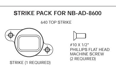
640 TOP AND BOTTOM STRIKE
#10 X 1/2" PHILLIPS FLAT HEAD MACHINE SCREW (4 IN PACK FOR TOP AND BOTTOM STRIKE)
1 pcs)
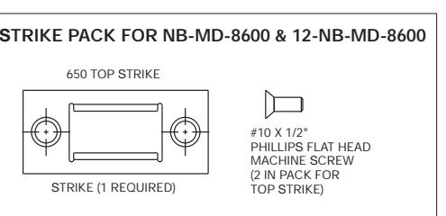
STRIKE PACK FOR AD-8600 STRIKE PACK FOR MD-8600 & 12-MD-8600
rod assembly
A
Bottom bolt & rod assembly
Inner chassis
C
Manual dogging key (not used with 12-) To operate: Depress push
rail, insert hex key (or cylinder key when used) and turn clockwise.
Not furnished with 12-MD8600
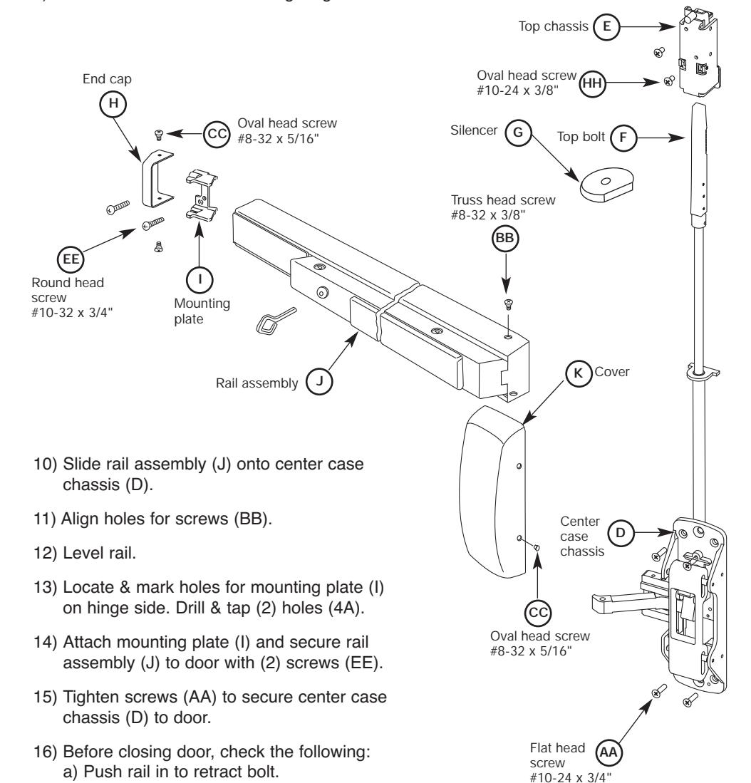
- 8) Slide rod silencer (G) over Top Bolt (F) onto rod, followed by top chassis (E). Secure top chassis (E) to door with (2) screws (HH) using holes (1A).
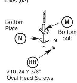
- 9A) For AD-8600 bottom bolt: Install bottom plate (N) over bottom bolt (M) and secure with (2) screws (HH) using holes (6A).
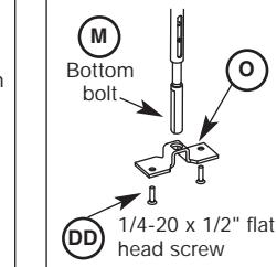
9B) For MD-8600 & 12-MD-8600: Install bottom plate (O) over bottom bolt (M) and secure with (2) screws (DD)
18) For AD-8600: Attach 640 strike using instruction sheet A8037 supplied with strike pack.
d) Bolt engagement with strike 1/4"- 5/16".
e) Adjust bolts per steps 7A & 7B.
19) For MD-8600 & 12-MD-8600: Attach 650 top strike to frame with two #10-24 x 1/2" flat head screws & 606 bottom strikes with anchors supplied and two 1/4-20 x 2" flat head screws. (See chart on left)
top of door hits frame.
- 20) Attach cover (K) to center case chassis (D) with (4) screws (CC).
- 21) Attach end cap (H) to mounting plate (I) with (2) screws (CC).
- 22) Secure rail assembly (J) to chassis (D) with (2) screws (BB).
For AD-8600 Bottom Bolt Install bottom plate (N) over the bottom bolt (M) and secure with two #10-24 x 3/8" oval head screws (DD) using holes (6A)
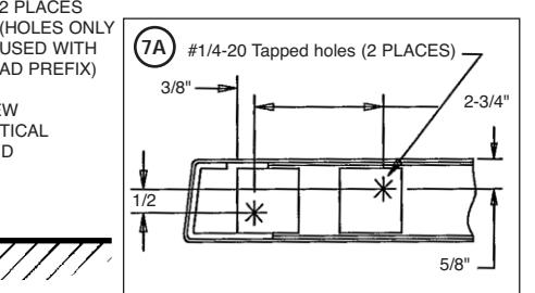
For MD-8600 & 12-MD-8600 Bottom Bolt Install bottom plate (O) over the bottom bolt (M) and secure with two 1/4-20 x 1/2" flat head screws (GG) using tapped holes (7A)
Top chassis
E
Copyright © 2008, 2009 Sargent Manufacturing Company, an ASSA ABLOY Group company. All rights reserved. Reproduction in whole or in part without the express written permission of Sargent Manufacturing Company is prohibited.
Plate
BEVEL
OF CHASSIS
5/8"
1-1/4"
5A
1/4" 7/8"
1-1/4"
ONLY
POSITION OF MOUNTING SCREW HOLES ARE IDENTICAL FOR EITHER HAND
7/32" DIA. C'SINK FOR #10 SCREW
Instructions for Installing NB-AD-8600, NB-MD-8600 & 12-NB-MD-8600 Concealed Vertical Rod Exit Devices without Bottom Bolt
For additional information, contact SARGENT at 1-800-727-5477
Verify the correct exit device is being installed on the correct door. Function, finish and size should all be verified.
Note: Before removing door from hinges determine the gap between top of door and frame. This information is needed for step #7. Remove door from the frame.
1) Drill, tap & c'sink the door per template, except
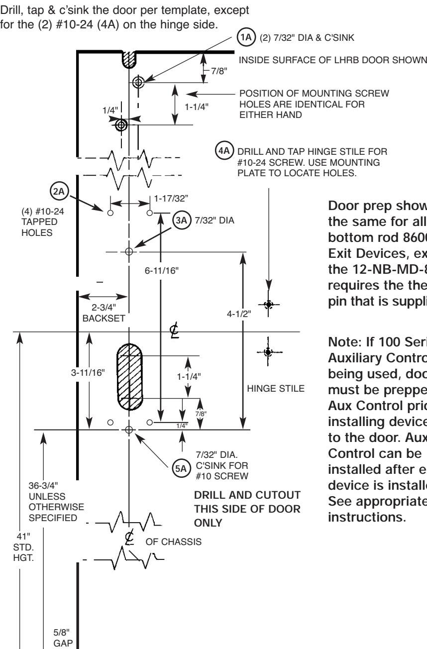
Door prep shown is the same for all less bottom rod 8600 Exit Devices, except the 12-NB-MD-8600 requires the thermal pin that is supplied.
Note: If 100 Series Auxiliary Control is being used, door must be prepped for Aux Control prior to installing device on to the door. Aux Control can be installed after exit device is installed. See appropriate instructions.
-
INSIDE LEFT HAND REVERSE BEVEL RIGHT HAND REVERSE BEVEL THIS EXIT DEVICE IS HANDED CHECK HAND OF DEVICE AGAINST APPLICATION OUTSIDE
- Information for Cutting Rails Rail Sizes Door Widths Max Min E 32" 24" F 36" 33" J 42" 37" G 48" 43"
- 2) Screw top bolt & rod assembly (A) into inner chassis (B).
- 3) Slide complete assembly into top of door.
- 4) Attach inner chassis (B) to door with screw (GG) using hole (5A).
- 5) Then secure with screw (FF) using hole (3A).
- 6) Position chassis (D) over fillister head screw and attach to door with (4) screws (AA) using holes (2A). Do not tighten yet. Use chassis (D) to retract top bolt & rod assy (A) to adjust bolt projection.
Note: Rod must be retracted while adjusting bolt projection. Use chassis (D) to retract top bolt & rod assy (A).
Top bolt & rod assembly
A
#10-24 x 1/2"
Manual dogging key (not used with 12-) To operate: Depress push rail, insert hex key (or cylinder key when used) and turn
Not furnished with 12-MD8600
clockwise.
7) Adjusting the top bolt & rod assembly (A)
- 1) 1/8" gap or less between door top and frame. Rotate bolt to make even with top of the door.
- 2) 1/8" gap or greater. Bolt to extend above door equal to gap minus an 1/8".
|
AA
Chas sis m ing s ount crew l doo licati meta r app on (#10- 24 x 3/4" ph. fl .hd. mach ws, 4 pcs) . scre |
BB
Rail m ount ing s crew (#8-3 /8" p 2 x 3 h. tru ss head hine mac screw pcs) by fin ish 2 |
CC
Cove nd ca untin r & e p mo g (#8- 32 x 5/16" with screw #6 p h. ov . u'cu t hd. mach ine ) , by f inish 6 pcs screw |
|---|---|---|
|
FF
Align ing a nd in hass is ner c (#10 3/8" ph. -24 x screw filliste r hd. mach ine s crew , ) 1 pcs |
EE
End c ing b racke ount t ap m (#10- 24 x 3/4" ph. rd hd. m ach. 4 pc s) screw |
HH
Top nting case mou scre w (#10- 3/8" 24 x ph. o v. hd s) hine 2 pc mac screw |
|
GG
Inner chas sis b ottom scre w strik & top e scr ews (#10- 24 x 1/2" ph. fl .hd.m ach. cs) s, 3 p screw |
ET m
ount ing s crew (1/4" -20 x 2 3/ 8" ph . fl. h d. cs) mach w 2 p . scre For 1 3/4" doo r leng th show n size varie s by 1/4" depe nding idth o f on w cladd ing o r insi de pa nel |
8) Slide rod silencer (G) over top bolt (F) onto rod, followed by top chassis (E). Secure top chassis (E) to door with (2) screws (HH) using holes (1A).
9) Install door into the frame using hinges.
Note: 12-NB-MD8600 Series Exit Devices require installation of thermal pin to meet requirements for fire rating.
18) For NB-MD-8600 and 12-NB-MD-8600: Attach 650 top strike to frame with two #10-24 x 1/2" flat head screws. See chart on left.
instruction sheet A8037 supplied with strike pack.
- 19) Attach cover (K) to center case chassis (D) with (4) screws (CC).
- 20) Attach end cap (H) to mounting plate (I) with (2) screws (CC).
b) Bolt stays retracted (Hold Back). c) Bolt releases when door closes. Button
d) Bolt engagement with strike 1/4"- 5/16".
17) For NB-AD-8600: Attach 640 strike using
inside top of door hits frame.
e) Adjust bolts per step 7.
21) Secure rail assembly (J) to chassis (D) with (2) screws (BB).
Copyright © 2008, 2009 Sargent Manufacturing Company, an ASSA ABLOY Group company. All rights reserved. Reproduction in whole or in part without the express written permission of Sargent Manufacturing Company is prohibited.
FINISHED FLOOR