AD AND MD-8400 INSTRUCTIONS 8400, NB8400, 12-MD8400, 12-NB-MD8400 Narrow Concealed Vertical Rod Exit Device Installation Instructions (8400)
Open the original PDF document
View PDFInstructions for Installing AD-8400, MD-8400 & 12-MD-8400 SARGENT Series Concealed Vertical Rod Exit Device
ASSA ABLOY
Verify that the correct exit device is being installed on the correct door. Function, finish and size should all be verified. Note: Before removing door from hinges, determine the gap between top of door and frame. Determine smallest gap between bottom of door and high point of floor or threshold as door swings. This information is needed for step #7. Remove door from the frame.
1) Drill, tap & c'sink the door per template, except for the (2) #10-24 (4A) on the hinge side.
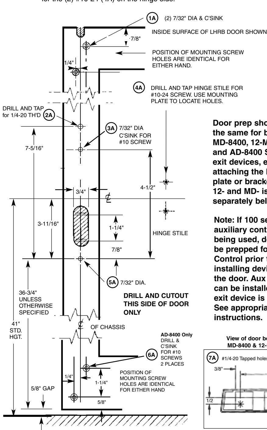
Door prep shown is the same for both the MD-8400. 12-MD-8400 and AD-8400 Series exit devices, except for attaching the bottom plate or bracket. 12- and MD- is shown separately below.
Note: If 100 series auxiliary control is being used, door must be prepped for Aux Control prior to installing device on to the door. Aux Control can be installed after exit device is installed. See appropriate
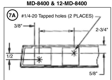
View of door bottom for MD-8400 & 12-MD-8400
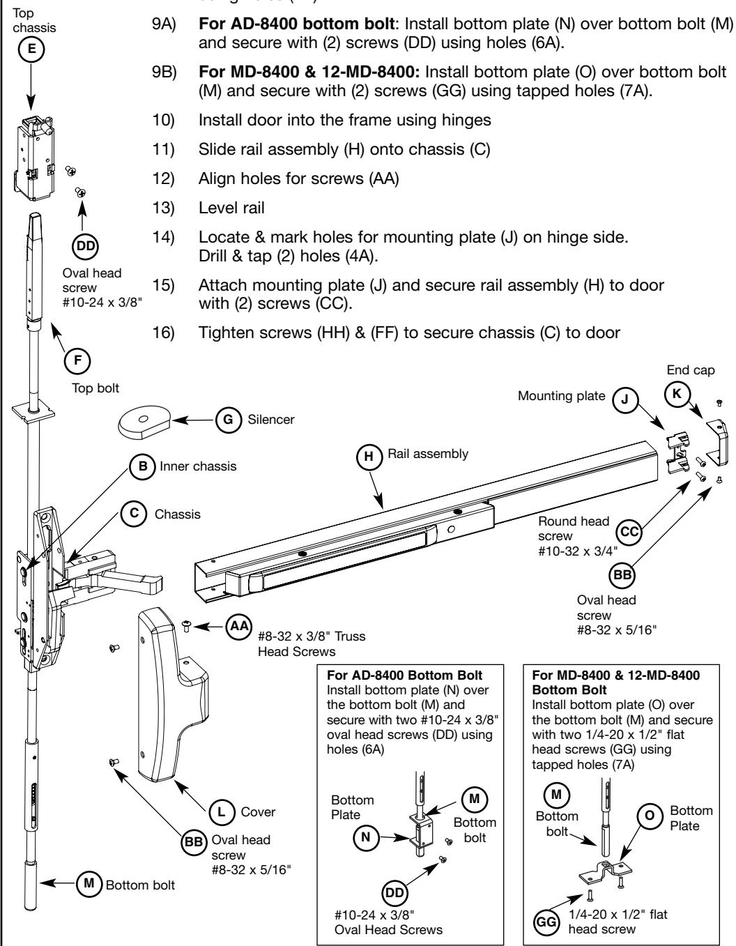
THIS EXIT DEVICE IS HANDED CHECK HAND OF DEVICE AGAINST APPLICATION I FFT HAND RIGHT HAND OUTSIDE BEVEL BEVEL
FINISHED FLOOR
| Information for Cutting Rails | ||||
|---|---|---|---|---|
| Rail Sizes | Door Widths | |||
| nali Sizes | Max | Min | ||
| E | 32" | 24" | ||
| F | 36" | 33" | ||
| J | 42" | 37" | ||
| G | 48" | 43" | ||
- 2) Screw top bolt & rod assembly (A) and bottom bolt & rod assembly (D) into inner chassis (B).
- Slide complete assembly into top of door.
- Attach inner chassis (B) to door with screw (EE) using hole (3A).
Note: If 700 Series ET Control is being used, it must be installed at this point, prior to step 5. See appropriate instructions.
- Position chassis (C) over fillister head screw (EE) and attach to inner chassis (B) using hole (5A) with washer (JJ) & screw (HH). Do not tighten yet.
- Secure top of chassis (C) to door with screw (FF) using tapped hole (2A). Do not tighten yet. Use chassis (C) to retract top bolt & rod assy (A) & bottom bolt & rod assy (D) to adjust bolt projection.
Note: Rods must be retracted while adjusting bolt projection. Use chassis (C) to retract top bolt & rod assy (A) & bottom bolt & rod assy (D)

- 1) 1/8" gap or less between door top and frame. Rotate bolt to make even with top of the door
- 2) 1/8"gap or greater. Bolt to extend above door equal to gap minus 1/8"
7B) Adjusting the bottom bolt & rod assembly
- 1) 1/8"gap or less between door bottom & high point. Rotate bolt to make even with bottom of door
- 2) 1/8"gap or greater. Bolt to extend below door equal to gap minus 1/8"
(not used with 12-)
#8-32 x 3/8" PHILLIPS
TRUSS HEAD
MACHINE SCREW
For additional information, contact SARGENT at 1-800-727-5477
4 IN PACK FOR END CAR
⊐ (нн)
MACHINE SCREW (1 IN PACK FOR OUTER CHASSIS TO INNER CHASSIS)
MOUNTING BRACKET
PHILLIPS FLAT HEAD
#10 - 24 X 3/4"
#10-24 X 3/4"
PHILLIPS OVAL HEAD
MACHINE SCREW
STAR WASHER
#10 - 24 X 3/8"
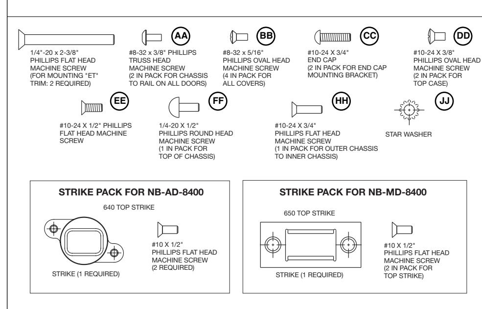
SCREWS USED FOR AD-8400, MD-8400 AND 12-MD-8400 EXIT DEVICE INSTALLATION
#8-32 x 5/16"
MACHINE SCREW
PHILLIPS FLAT HEAD
1/4-20 X 1/2"
BOTTOM PLATE
PHILLIPS OVAL HEAD
Top bolt & rod
© Chassis
(FF) head
Round
1/4-20 x 1/2'
Inner
chassis
(B)
#10-24 x 1/21 Phillips flat head
PHILLIPS FLAT HEAD
#10 X 1/2"
PHILLIPS FLAT HEAD
MACHINE SCREW
MACHINE SCREW
machine screws
Bottom bolt & rod
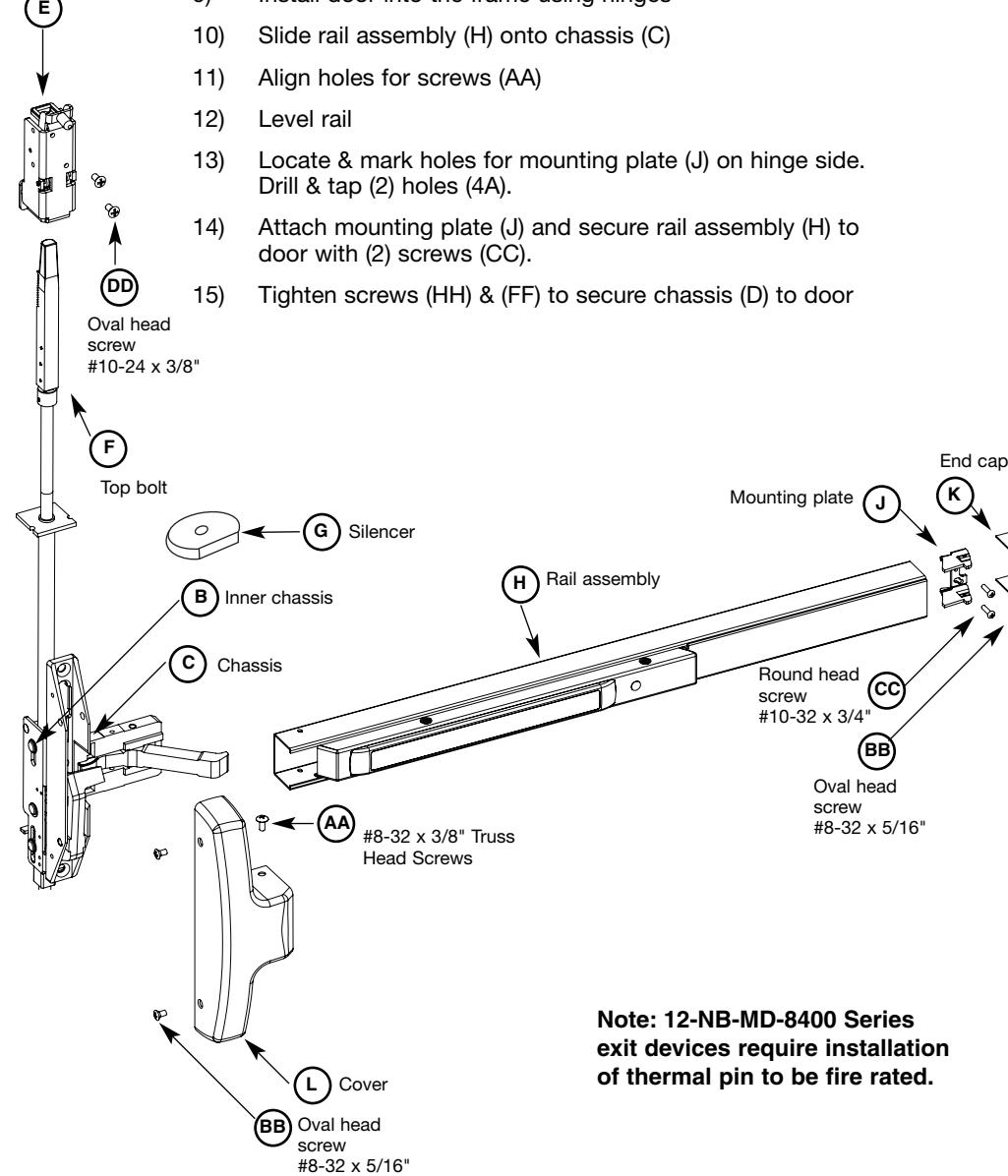
Slide rod silencer (G) over top bolt (F) onto rod, followed by top chassis (E). Secure top chassis (E) to door with (2) screws (DD) using holes (1A).
-
Before closing door, check the following:
- a) Push rail in to retract bolts
- b) Bolts stay retracted (hold back)
- c) Bolts release when door closes. Button inside top of door hits frame
- d) Bolt engagement with strike 1/4"- 5/16"
- e) Adjust bolts per steps 7A & 7B)
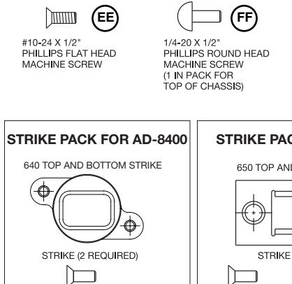
- For AD-8400: Attach 640 strike using instruction sheet A8037 supplied with strike pack.
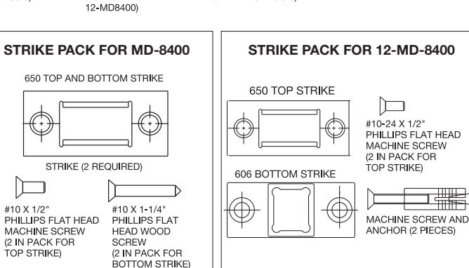
- For MD-8400: Attach 650 top strike to frame with two #10-24 x 1/2" flat head screws & 650 bottom strike with anchors supplied and two #10 x 1-1/4 flat head wood screws. (See chart on left)
- For 12-MD-8400: Attach 650 top strike to frame with two #10-24 x 1/2" flat head screws & 606 bottom strikes with anchors supplied and two 1/4-20 x 2" flat head screws. (See chart on left)
- Position cover (L) on chassis (C) and secure with (2) screws (BB)
- Attach end cap (K) to mounting plate (J) with (2) screws (BB)
- Secure rail assembly (H) to chassis (C) and cover (L) with (2) screws (AA)
Instructions for Installing NB-AD-8400, NB-MD-8400, & 12-NB-MD-8400 Series Concealed Vertical Rod Exit Device
Verify that the correct exit device is being installed on the correct door. Function, finish and size should all be verified. Note: Before removing door from hinges, determine the gap between top of door and frame. This information is needed for step #7. Remove door from the frame.
1) Drill, tap & c'sink the door per template, except for the (2) #10-24 (4A) on the hinge side.
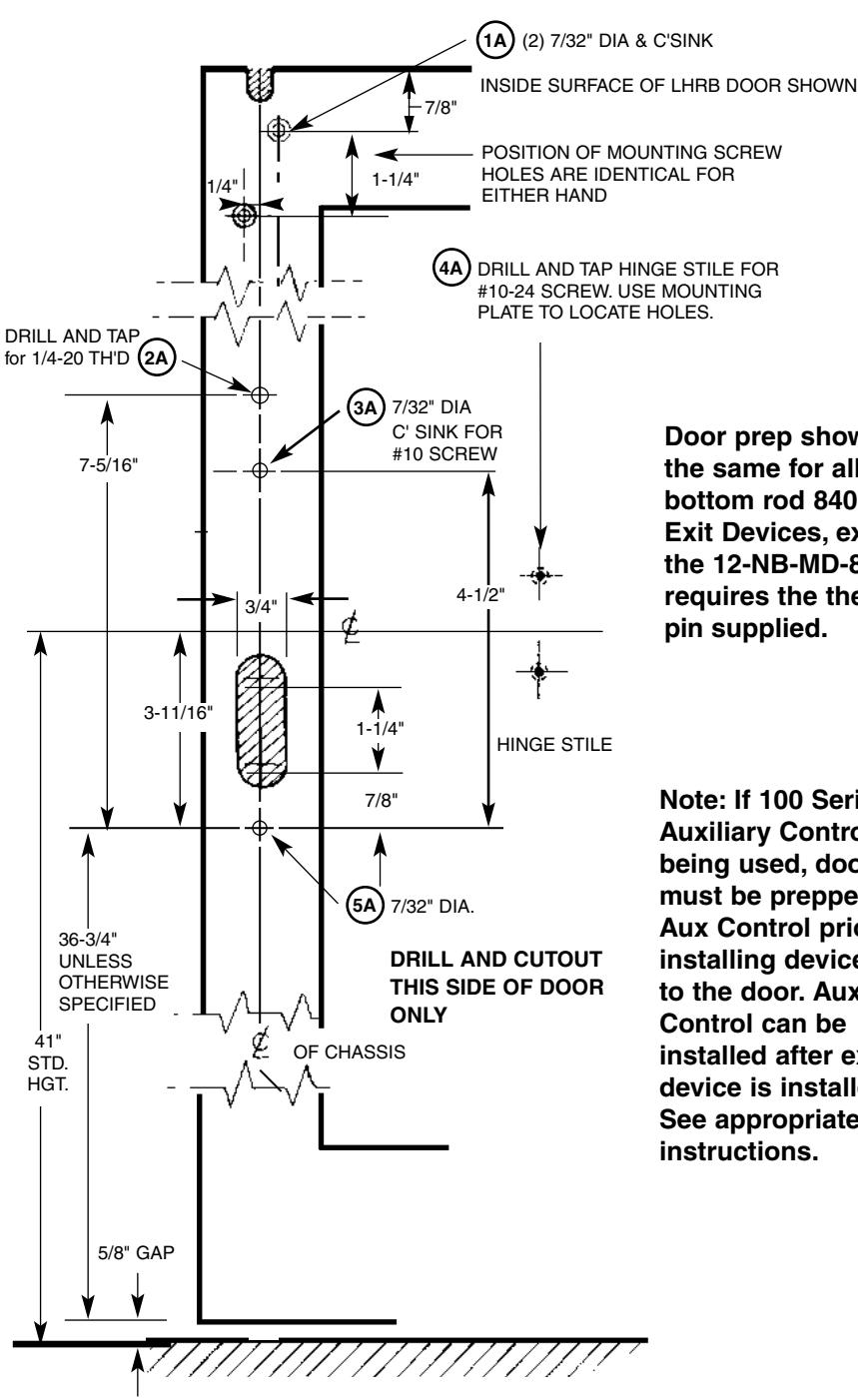
- Door prep shown is the same for all less bottom rod 8400 Exit Devices, except the 12-NB-MD-8400 requires the thermal pin supplied.
- Note: If 100 Series Auxiliary Control is being used, door must be prepped for Aux Control prior to installing device on to the door. Aux Control can be installed after exit device is installed. See appropriate instructions.
OUTSIDE INSIDE LEFT HAND REVERSE BEVEL RIGHT HAND REVERSE BEVEL THIS EXIT DEVICE IS HANDED CHECK HAND OF DEVICE AGAINST APPLICATION
FINISHED FLOOR
| Information for Cutting Rails | |||
|---|---|---|---|
| Rail Sizes | Door Widths | ||
| Max | Min | ||
| E | 32" | 24" | |
| F | 36" | 33" | |
| J | 42" | 37" | |
| G | 48" | 43" | |
2) Screw top bolt & rod assembly (A) into inner chassis (B).
Round head screw 1/4-20 x 1/2"
Chassis
FF
HH
Top bolt & rod assembly
Inner chassis
B C
A
#10-24 x 1/2" Phillips flat head machine screws
EE
- 3) Slide complete assembly into top of door.
- 4) Attach inner chassis (B) to door with screw (EE) using hole (3A).
Note: If 700 Series ET Control is being used, it must be installed at this point, prior to step 5. See appropriate instructions.
- 5) Position chassis (C) and attach to inner chassis (B) using hole (5A) with washer (JJ) & screw (HH). Do not tighten yet.
- 6) Secure top of chassis (C) to door with screw (FF) using tapped hole (2A). Do not tighten yet. Use chassis (C) to retract top bolt & rod assy (A) to adjust bolt projection.
Note: Rod must be retracted while adjusting bolt projection. Use chassis (C) to retract top bolt & rod assy (A).
-
7)
Adjusting the top bolt & rod assembly (A):
- 1) 1/8" gap or less between door top and frame. Rotate bolt to make even with top of the door
- 2) 1/8"gap or greater. Bolt to extend above door equal to gap minus 1/8"
For additional information,
contact SARGENT ® at 1-800-727-5477
SCREWS USED FOR NB-AD-8400, NB-MD-8400 AND 12-NB-MD-8400 EXIT DEVICE INSTALLATION
- 8) Slide rod silencer (G) over top bolt (F) onto rod, followed by top chassis (E). Secure top chassis (E) to door with (2) screws (DD) using holes (1A).
- 9) Install door into the frame using hinges
Top chassis
-
16) Before closing door, check the following:
- a) Push rail in to retract bolt
- b) Bolt stays retracted (hold back)
- c) Bolt releases when door closes. Button inside top of door hits frame
- d) Bolt engagement with strike 1/4"- 5/16"
- e) Adjust bolts (per step 7)
- 17) For NB-AD-8400: Attach 640 strike using instruction sheet A8037 supplied with strike pack.
- 18) For NB-MD-8400 and 12-NB-MD-8400: Attach 650 top strike to frame with two #10-24 x 1/2" flat head screws. See chart on left.
- 19) Position cover (L) on chassis (C) and secure with (2) screws (BB)
- 20) Attach end cap (K) to mounting plate (J) with (2) screws (BB)
- 21) Secure rail assembly (H) to chassis (C) and cover (L) with (2) screws (AA)