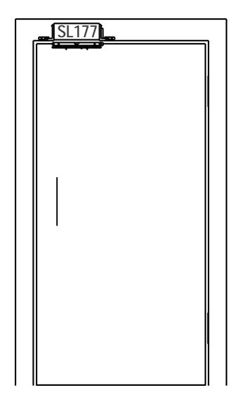
ACSI Mounting Instructions for Asterix Series Electromagnetic Locks Model 177SL – 3795 Series
Open the original PDF document
View PDFMODEL 177SL
MOUNTING INSTRUCTIONS FOR ASTERIX SERIES ELECTRO-MAGNETIC LOCKS
IMPORTANT! READ THOROUGHLY BEFORE ATTEMPTING INSTALLATION. DO NOT DAMAGE OR MARK MAGNETIC LOCK OR ARMATURE FACE-MAY REDUCE HOLDING EFFICIENCY.
The SHEAR Electro-magnetic lock, although it provides aesthetics through concealment, is less forgiving than the regular pull type magnetic lock where alignment problems between the door and frame exists.
Careful and proper preparation / installation of the door frame, door, door hardware, and shear lock must be taken to attain positive lock action and trouble free operation.
Areas on each side of the door must not be pressurized, to insure the door will return to its closed position every time.
A high quality door closer should be used to ensure the door returns to its positive closed position, if the door is double acting, the door should be adjusted to sit in its positive center position.
All door latching problems should be corrected prior to installation.
PREPARATION:
Make sure there is a clearance of 1/8" (3 mm) between the top of the door and the bottom of the header. Make any adjustments, if required.
Adjust single acting door and door closer to close positively and rest against the door stop, taking into consideration any other door accessories, for example weather stripping, mutes and door seals.
Adjust double acting doors and door closer to close positively and settle at the centered position.
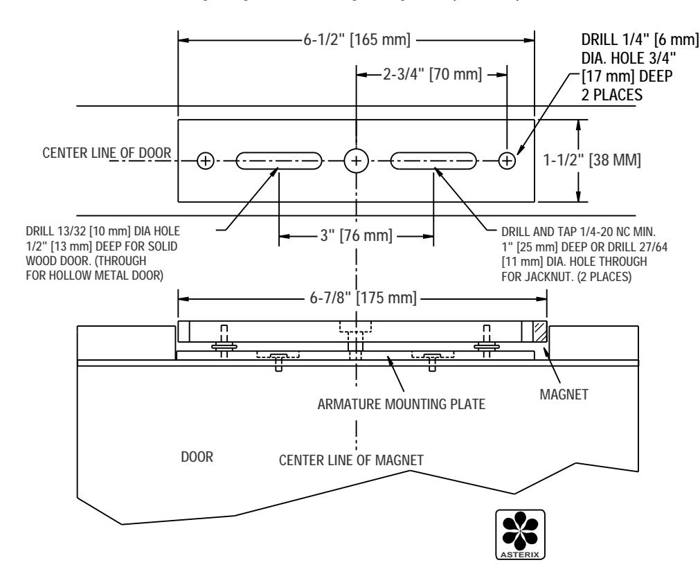
Locate the vertical center-line of the shear lock assembly and armature as close as possible to the lock edge, without interfering with any other door hardware.
Locate the horizontal center-line of the door, the centerline of the armature will be the same.
Mark the door as shown in the template.
To determine the frame header center-line; Single acting door must be in fully closed position, and positively rest against the door stop. Double acting door must be fully closed and dead stop positively in the dead center of the frame.
Transfer the door horizontal center-line to the frame to determine the frame center-line.
Mark the frame header per the template and prepare the door and frame accordingly.
WIRING THE SL177 SHEAR MAGNETIC LOCK:
The SL177 magnetic lock is supplied with a DCM-4 delay module.
The DCM-4 delay module is designed to provide electronic logic to lock and unlock doors with time adjustment to release and relock the door upon reactivation signals.
ADJUSTMENT #1 — Door Unlock Time Adjustment:
Momentary activation of the release switch or a normally open contact will de-energize the magnetic lock for a pre-determined period of time (0-45 seconds). If the door is opened and closed within the adjusted time period, the door will reset and relock after passing through the delay relock phase (see Adjustment #2). However, if the door is still not closed after the preset time set in adjustment #1, the magnetic lock will not reenergize until the door has been returned to its proper closed position.
ADJUSTMENT #2 — Delay Relock Time Adjustment:
This is the preset time to delay re-energizing the lock after the door is seated in its proper closed position (time adjustable from 0-45 seconds, adjustment to 0 will disable this feature).
INSTALLATION:
Install the SL177 shear lock magnetic lock assembly and armature assembly with the door position switch toward the lock edge of the door.
For trouble free operation , the armature must be adjusted upwards toward the lock face parallel and as close as possible, without interfering with the opening and closing cycle.
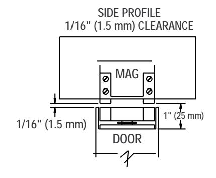
Optimum clearance with the magnet face and finish armature is 1/16" (1.5 mm). Use hex key and the extra shims provided to adjust the height for proper operation.
Turn lock power on when the door is closed, and check lateral alignment. Armature should draw up and sit snugly on the magnet face between the legs of the shear bracket.
If clearance is sufficient for proper drawing of the armature plate, cycle the doors to ensure the unit will positively lock and unlock each time.
If positive locking cannot be attained, check clearance and alignment again, then correct and repeat testing operation.

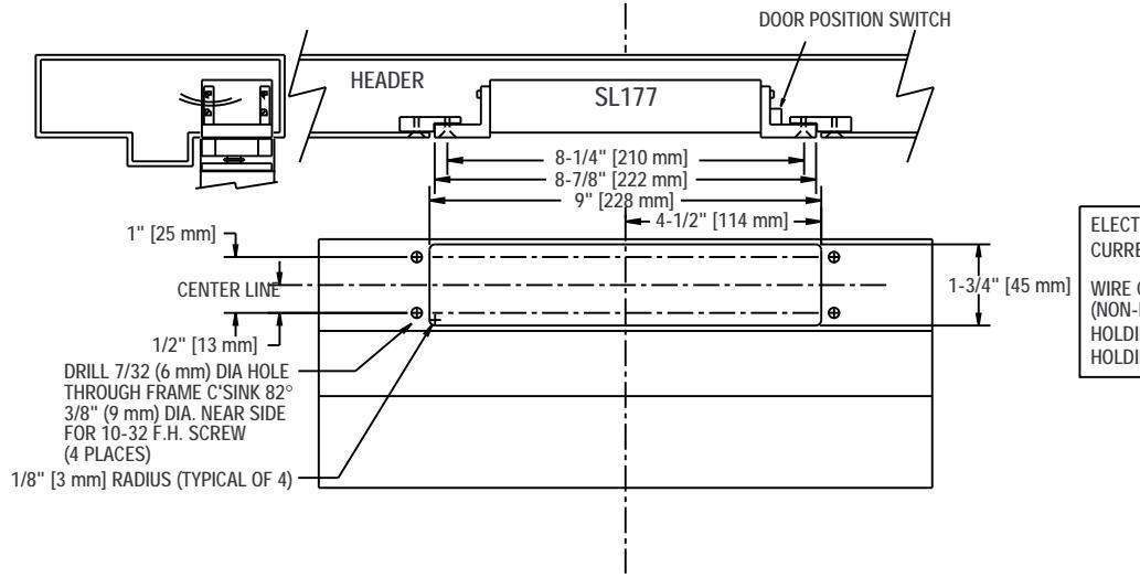
ELECTRICAL SPECIFICATIONS:
CURRENT DRAW: 0.50 AMPS @ 12 VDC
0.25 AMPS @ 24 VDC
WIRE COLOR CODE: ORANGE/ORANGE (12VDC)
(NON-POLARIZED) RED/RED (24VDC) HOLDING FORCE: 600 LB (272 KG) HOLDING FORCE: 1200 LB (544 KG)
DOOR UNLOCK TIME ADJUSTMENT (ADJUSTABLE 0-45 SECONDS) MOMENTARY ACTIVATION OF THE RELEASE SWITCH WILL UNLOCK THE DOOR FOR A PRE-DETERMINED PERIOD. IF THE DOOR IS OPENED DURING THIS RELEASE, THE REST OF THE UNLOCK TIME WILL BE RESET. HOWEVER, THE MAGNET WILL NOT BE RE-ENERGIZED UNTIL THE DOOR IS IN ITS PROPER CLOSED POSITION.
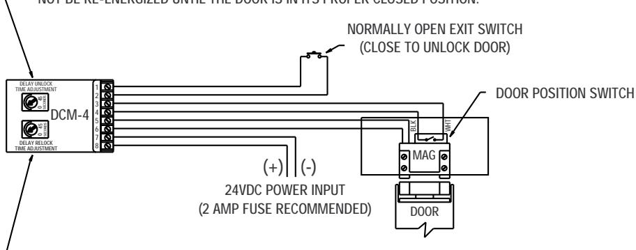
DELAY LOCK UPON DOOR LATCHING TIME ADJUSTMENT. WHEN THE DOOR IS RETURNED TO THE CLOSED POSITION, THE DOOR CONTACT WILL ACTIVATE A PRE-DETERMINED DELAY RELOCK TIME. THIS DELAY WILL ALLOW THE DOOR TO BE PROPERLY SEATED BEFORE THE MAGNET IS ENERGIZED. (ADJUSTABLE 0 - 45 SECONDS, SETTING THE TIME TO 0 WILL DISABLE THIS FEATURE)
DCM-4 TERMINALS
1,2 REQUEST TO EXIT SWITCH (N.O.) 3,4 DOOR POSITION SWITCH (CLOSED) 5,6 OUTPUT POWER TO MAGNETIC
LOCK (24VDC)/12 VDC 7,8 24/12 VDC INPUT POWER (7-NEG, 8-POS)
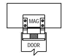
MAGNET IS ENERGIZED AND THE DOOR IS PROPERLY LOCKED.
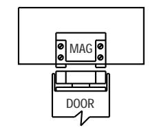
MAGNET IS DE-ENERGIZED AND THE DOOR IS UNLOCKED.

ASTERIX SECURITY HARDWARE INTERNATIONAL INC.
7045 Tranmere Drive Unit 10 Mississagua Ontario Canada L5S 1M2 Phone: (905) 672-1245 Fax: (905) 672-1247 U.S. Phone/Fax.: (630) 350-7599
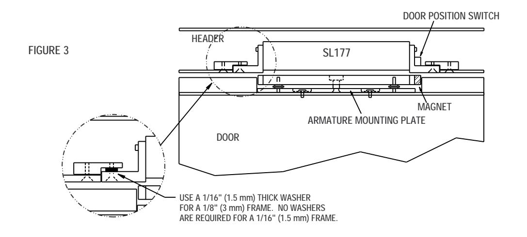
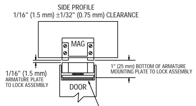
FOR DOORS WITH GREATER THAN 1/16" (1.5 mm) GAP, EITHER APPLY SHIMS AS NECESSARY TO REDUCE THE GAP TO 1/16" (1.5 mm) BETWEEN THE ARMATURE PLATE ANDTHE MAGNETIC LOCK ASSEMBLY, OR DO NOT MORTISE THE DOOR AS DEEP, SO AS TO PROVIDETHE NECESSARY 1/16" (1.5 mm) GAP BETWEEN THE ARMATURE PLATE AND THE MAGNETIC LOCK ASSEMBLY.
DRILL 1/4" [6 mm] DIA. HOLE 3/4" [17 mm] DEEP. (2 PLACES)
ASTERIX SECURITY HARDWARE INTERNATIONAL INC.
7045 Tranmere Drive Unit 10 Mississagua Ontario Canada L5S 1M2 Phone: (905) 672-1245 Fax: (905) 672-1247 U.S. Phone/Fax.: (630) 350-7599
NOTES:
- 1. VERTICAL CENTER LINE (MAGNET AND ARMATURE) SHOULD BE LOCATED AS FAR FROM THE HINGE SIDE OF THE DOOR AS POSSIBILE. (ADJUST THIS LINE SO THAT THE MOUNTING OF THE ARMATURE PLATE AND MAGNET ARE FREE FROM STRUCTURAL INTERFERENCE.)
- 2. HORIZONTAL CENTER LINE IS DETERMINED BY THE DOOR'S THICKNESS. TRANSFER THIS LINE TO THE TOP JAMB OF THE DOOR FRAME. TOGETHER WITH THE VERTICAL CENTER LINE, THE CENTER OF THE MAGNET AND ARMATURE MOUNTING PLATE CAN BE DETERMINED.
CAUTION:
ON FRAME WITH A STOP, LOCATE HEADER CENTER LINE ON TOP JAMB WITH SLIGHT CLEARANCE BETWEEN THE DOOR AND THE STOP TO ENSURE FREE LOCKING ACTION.
3. IF THE DOOR'S TOP RAIL MATERIAL IS NOT SUFFICIENT TO SUPPORT THE ARMATURE PLATE, JACKNUTS SHOULD BE USED.
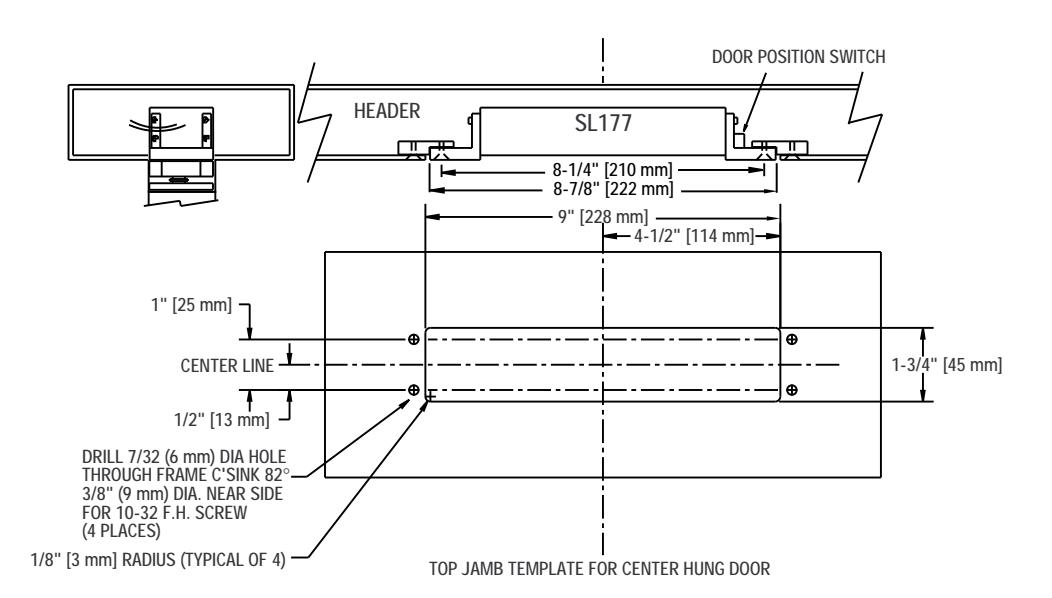
ELECTRICAL SPECIFICATIONS:
CURRENT DRAW: WIRE COLOR CODE: (NON-POLARIZED) RED/RED (24VDC) 0.50 AMPS @ 12 VDC 0.25 AMPS @ 24 VDC ORANGE/ORANGE (12VDC)
HOLDING FORCE (PULL): 600 LB (272 KG) HOLDING FORCE (SHEAR): 1200 LB (544 KG)
TOP JAMB TEMPLATE FOR OFFSET HUNG DOOR
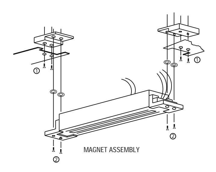
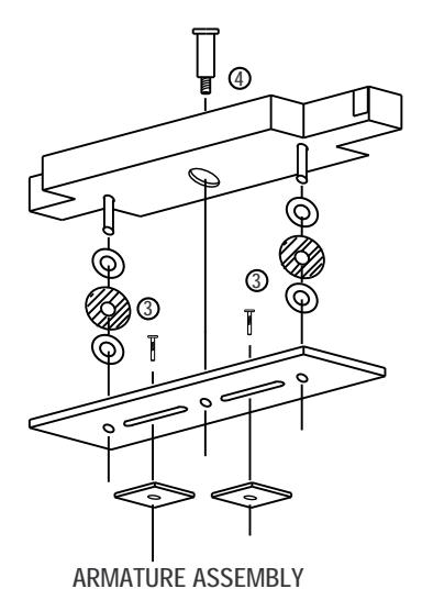
INSTALLATION SHOULD PROCEED FOLLOWING STEPS 1 THROUGH 4 ON THE ASSEMBLY DIAGRAM TO THE LEFT.
THICKNESS AND RAIL DEPTH USE NECESSARY SHIMS TO ACHIEVE PROPER INSTALLATION. NOTE: CHECK DOOR FRAME

ASTERIX SECURITY HARDWARE INTERNATIONAL INC.
7045 Tranmere Drive Unit 10 Mississagua Ontario Canada L5S 1M2 Phone: (905) 672-1245 Fax: (905) 672-1247 U.S. Phone/Fax.: (630) 350-7599