ACSI Mounting Instructions for Asterix Series Electromagnetic Locks Model 175 – 3780 Series
Open the original PDF document
View PDFMODEL 175
MOUNTING INSTRUCTIONS FOR ASTERIX SERIES ELECTRO-MAGNETIC LOCKS
IMPORTANT! READ THOROUGHLY BEFORE ATTEMPTING INSTALLATION. DO NOT DAMAGE OR MARK MAGNETIC LOCK OR ARMATURE FACE-MAY REDUCE HOLDING EFFICIENCY.
See Figure 1 elevation profiles to determine mounting application requirements for each individual application.
NOTE: A 2-1/2" (64 MM) REVEAL IS REQUIRED TO ASSURE RIGID MOUNTING OF THE 175 SERIES MAGNETIC LOCK ASSEMBLY.
STEP 1. Mark door(s) according to armature template and dimensions on reverse side.
STEP 2. Drill and prep holes in door per armature template on reverse side.
STEP 3. Gently tap (2) 3/16" (5 mm) DIA. spring pins into rear side of armature(s).
STEP 4. Insert one (1) spring washer over 5/16"-18 "special" shoulder screw, insert screw through armature(s). Add three (3) conical spring washers and one (1) flat washer over shoulder screw(s). See Figure 2 - details for each type of installation. All parts must be assembled properly before installing armature to door. Install complete armature assembly on door per Figure 2 details.
STEP 5. Tighten shoulder screw(s) securely with allen wrench. (Do not overtighten.)
NOTE: ALL ARMATURES ARE NORMALLY EQUIPPED WITH A PERMANENT MAGNET ON ONE END. BE CERTAIN TO INSTALL ARMATURE SO MAGNET LINES UP WITH MAGNETIC SWITCH INSIDE HOUSING OF MAGNETIC LOCK ASSEMBLY, SEE FIGURE 3.
STEP 6. Mark frame per magnetic lock template and dimensions on reverse side.
STEP 7. Remove housing cover of Magnetic Lock Assembly.
STEP 8. Drill and prep frame per "D" of Magnetic lock template, attach Magnetic Lock Assembly to frame using either (2) #14 sheet metal screws or (2) 1/4"-20 machine screws and toothed lock washers, tighten only enough to hold unit in place. If filler plate is used, assure that screws go thru both filler plate and frame.
STEP 9. Drill 7/8" (22 mm) DIA. hole thru filler plate and frame per template for wiring harness.
STEP 10. Make all electrical connections per applicable wiring diagrams enclosed. Use wire nuts, crimp connectors or solder to assure good connections.
STEP 11. Energize Magnetic Lock Assembly; Adjust assembly so door is snug against door stop, tighten (2) preliminary screws securely.
STEP 12. De-energize system. Using mounting plate as template, drill-#21 drill and tap for 10-32 screws (minimum (2) places). (See Magnetic Lock Template) Install screws and tighten securely. Re-energize system, recheck alignment of Magnetic Lock Assembly to Armature by opening and closing door(s).
STEP 13. Install Magnetic Lock housing cover.

- A. For THRU BOLT mounting in hollow metal door(s) drill 11/32" (9 mm) DIA. hole thru door, enlarge hole in outside face to 1/2" (13 mm) DIA.
- B. For THRU BOLT mounting in solid core wood door(s), drill 11/32" (9 mm) DIA. hole thru door(s), enlarge hole in outside face to 1/2" (13 mm) DIA. 1" (25 mm) deep.
- C. For REINFORCED DOOR (Minimum 3/8" (10 mm) thickness) drill and tap thru reinforcement for 5/16-18 screw.
- D. Drill for No. 14 sheet metal screws or drill and tap for 1/4"-20 machine screws.
- E. Drill 7/8" (22 mm) DIA. hole thru filler (if used) and frame in either of locations marked (E) for wiring harness.
- F. Using actual Magnetic Lock as template, drill and tap per STEP 12 of installation instructions.
ARMATURE LOCATION BOTTOM EDGE OF STOP C BOTTOM EDGE OF STOP D.P.S. Magnet C C BOTTOM EDGE OF STOP C C BOTTOM EDGE OF STOP D.P.S. Magnet
.250 (6 mm) DIA. (38 mm) (32 mm) (32 mm) (38 mm) (38 mm) (38 mm) (38 mm) (38 mm) (38 mm) (38 mm) (38 mm) (38 mm) (38 mm) (38 mm) (38 mm) (39 PLACES (67 mm) (134 mm) REF.
MAGNETIC LOCK LOCATION
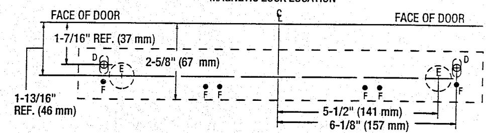
NOTE: FOR MACHINE SCREW MOUNTING; REINFORCEMENT AND STRUCTURING ARE REQUIRED TO WITHSTAND A 600 LB (272 KG) LOAD. CLEARANCE HOLES FOR FILLER PLATE TO BE SPOTTED AT JOB SITE. CAUTION: "DO NOT ATTACH MOUNTING PLATE TO FILLER PLATE ONLY!"
1" (25 mm)
MAGNETIC LOCK MOUNTING TO FRAME FIGURE 1
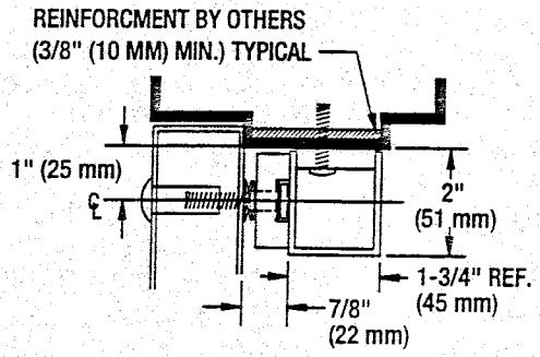

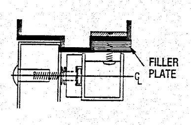
FIGURE 1B WITH SERIES 178 FILLER PLATE
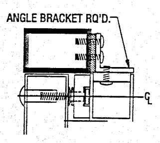
FIGURE 1C WITH 179 SERIES ANGLE BRACKET
ARMATURE MOUNTING TO DOOR(S) FIGURE 2
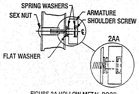
FIGURE 2A HOLLOW METAL DOOR
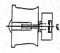
FIGURE 2B WOOD DOOR
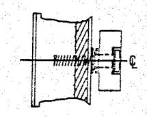
FIGURE 2C REINFORCED DOOR
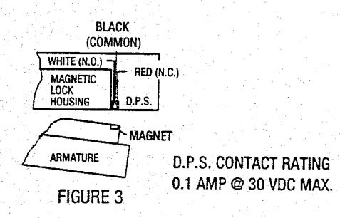
WIRING FOR D.P.S (DOOR POSITION SWITCH). DRAWING SHOWS DOOR IN OPEN POSITION
ELECTRICAL SPECIFICATIONS:
CURRENT DRAW:
0.50 AMPS @ 12 VDC
WIRE COLOR CODE:
0.25 AMPS @ 24 VDC ORANGE/ORANGE (12VDC)
(NON-POLARIZED) HOLDING FORCE:
RED/RED (24VDC) 600 LB (272 KG)
NOTE: Use with Underwriter Laboratories Listed (ULC/UL) Compatible Power Supply

ASTERIX SECURITY HARDWARE INTERNATIONAL INC.
7045 Tranmere Drive Unit 10 Mississagua Ontario Canada L5S 1M2 Phone: (905) 672-1245 Fax: (905) 672-1247
U.S. Phone/Fax.: (630) 350-7599