ACSI Mounting Instructions for Asterix Series Electromagnetic Locks Model 172 with Z Bracket Assembly – 3721 Series
Open the original PDF document
View PDFMODEL 172 WITH "Z" BRACKET ASSEMBLY
MOUNTING INSTRUCTIONS FOR ASTERIX SERIES ELECTRO-MAGNETIC LOCKS
IMPORTANT! READ THOROUGHLY BEFORE ATTEMPTING INSTALLATION. DO NOT DAMAGE OR MARK MAGNETIC LOCK OR ARMATURE FACE-MAY REDUCE HOLDING EFFICIENCY.
The Electro-Magnetic Lock Assembly mounts firmly and rigidly to the vertical face of the header on the pull side of the door. The Armature attaches to the 179 "Z" bracket assembly which is thru bolted to the door. The door and frame are flush to within 1/8" (3 mm). If the header projects more than 1/8" (3 mm) beyond the face of the door, a "special custom Z" bracket must be used in lieu of the 179. (Shimming the 179 bracket is NOT recommended.)
- STEP 1. Mark door(s) and frame for drilling and tapping in accordance with template dimensions on reverse side. All measurements are to be made with the door(s) in the closed position.
- STEP 2. Prep header for Magnetic Lock Assembly as shown on template on reverse side. Be sure header is adequately reinforced to hold mounting screws. If reinforcement has not been added, jack nuts, wingbolts or equivalent must be used. Drill hole for wiring per template.
- STEP 3. Remove housing cover of Magnetic Lock Assembly. Attach mounting angle to face of header, be sure that the right angle flange is on bottom for maximum shear resistance. Bottom of flange should be flush with rabbet in frame. Use all screws and lock washers provided.
- STEP 4. Prep door for "Z" bracket mounting assuring that bracket is centered on face of Magnetic Lock Assembly. All dimensions must be taken from the centerline of the from end of Magnetic Lock Assembly. On a double door application all dimensions doors or mullion. Drill (3) 3/8" (9 mm) DIA. holes through the doors per per template or
drill and tap for 12-24 thread if the doors have been properly reinforced. Mount the bracket to the pull side of the door.
STEP 5. Assemble Armature for mounting by pressing (2) spring pins into holes provided in one side of Armature, tap gently to firmly seat spring pins. Do not mar face of Armature. Insert (1) spring washer over shoulder screw and insert screw thru Armature as shown in details. Line up (2) spring pins with holes in "Z" bracket. Finish assembling Armature to "Z" bracket per details, assuring that the spring washers do not slip off of shoulder screw.
NOTE: ALL ARMATURES ARE NORMALLY EQUIPPED WITH A PERMANENT MAGNET MOUNTED IN ONE END FOR ACTUATING THE DOOR POSITION SWITCH ATTACHED TO ONE END OF THE MAGNETIC LOCK ASSEMBLY. BE CERTAIN THAT BOTH MAGNETS LINE UP DURING THE INSTALLATION PROCESS. MAKE NO ATTEMPT TO REMOVE EITHER OF THESE MAGNETS.
- STEP 6. Check Armature and Magnetic Lock Assembly for proper alignment. If Armature does not quite sit against face of Magnetic Lock Assembly, a second flat washer may need to be added to Armature assembly. If door does not quite close, one of the washers may be removed.
- STEP 7. Make all electrical connections.
- STEP 8. Energize system and re-check alignment of Magnetic Lock Assembly and Armature, by opening and closing doors. Make any adjustments if required.
- STEP 9. Install Magnetic Lock housing cover.

INSTALLATION TEMPLATE FOR MODEL 172 WITH "Z" BRACKET OPTION PULL SIDE MOUNTING (STANDARD)
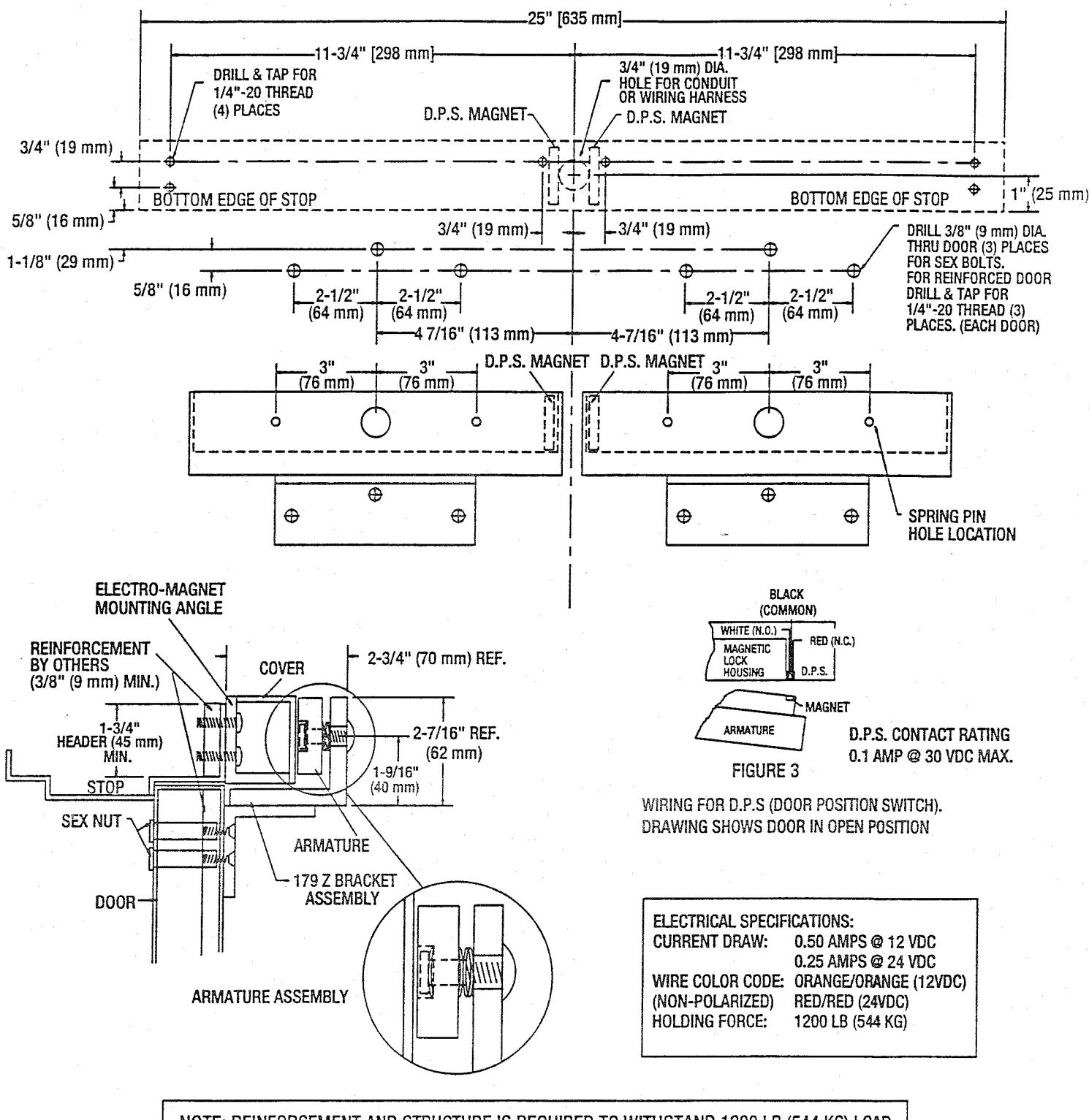
NOTE: REINFORCEMENT AND STRUCTURE IS REQUIRED TO WITHSTAND 1200 LB (544 KG) LOAD

NOTE: Use with Underwriter Laboratories Listed (ULC/UL) Compatible Power Supply
ASTERIX SECURITY HARDWARE INTERNATIONAL INC. 7045 Tranmere Drive Unit 10 Mississagua Ontario Canada L5S 1M2 Phone: (905) 672-1245 Fax: (905) 672-1247 U.S. Phone/Fax.: (630) 350-7599