ACSI Electric Exit Device K Switch Kit 130 – 1500 Series
Open the original PDF document
View PDF

ELECTRIC EXIT DEVICE KIT INSTALLATION INSTRUCTIONS AUTHORIZED EGRESS
K-130 JACKSON 20 SERIES
MONITORS THE USE OF THE TOUCH BAR
Electrical Specifications:
SPDT Monitor Switch Contacts Rated: 3A @ 125VAC 2A @ 30VDC
Wire Color Codes:
YELLOW - Common RED - Normally Open GRAY - Normally Closed
Installation:
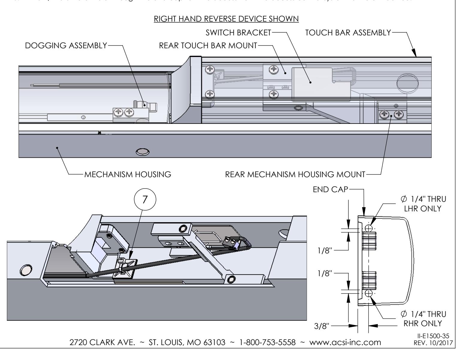
- 1. Separate the touch bar cover from the touch bar assembly.
- 2. Separate the touch bar assembly from the mechanism housing at the front and rear mechanism housing mounts.
- 3. Remove the rear touch bar mount from the touch bar assembly.
- 4. Locate the K-130 Kit between the rear touch bar mount and the touch bar assembly.
- 5. Attach the rear touch bar mount to the touch bar assembly. Verify the switch bracket is not prohibiting the rear touch bar mount from being secured flush to the touch bar assembly.
- 6. Route the lead wires along the side opposite of the dogging assembly location.
- 7. Secure the lead wires to the inside of the touch bar assembly using the supplied ty-wrap mount and ty-wrap.
- 8. Attach the touch bar assembly to the mechanism housing at the front and rear mechanism housing mounts.
- 9. Attach the touch bar cover to the touch bar assembly.
- 10. Drill a 1/4" diameter hole through the end cap for wire access from the access control system to the exit device.