ACSI Electric Exit Device Installation Instructions Authorized Egress K-131- II-E1500-44
Open the original PDF document
View PDF

ELECTRIC EXIT DEVICE KIT INSTALLATION INSTRUCTIONS AUTHORIZED EGRESS
K-131
FALCON 1690 AND 1790 SERIES FIRST CHOICE 3600 AND 3700 SERIES
MONITORS THE USE OF THE TOUCHBAR
Electrical Specifications:
SPDT Monitor Switch Contacts Rated: 3A @ 125VAC
2A @ 30VDC
Wire Color Codes:
YELLOW - Common RED - Normally Open GRAY - Normally Closed
Installation:
- 1. Separate the touchbar from the exit device.
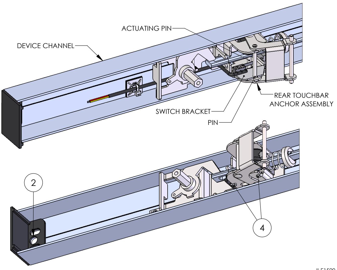
- 2. Drill a 3/8" diameter hole through the channel end cap and device channel for wire access from the access control system to the exit device.
- 3. Locate the K-131 Kit on the rear touchbar anchor assembly using the pin and flanges of the rear touchbar anchor assembly for positioning. Verify the switch arm is pre-actuated by the actuating pin of the rear touchbar anchor assembly.
- 4. Bend the tabs of the switch bracket to secure the switch bracket to the rear touchbar anchor assembly.
- 5. Route the lead wires along the outside edge of the device channel.
- 6. Secure the lead wires to the inside of the device channel using the supplied ty-wrap mount and ty-wrap.
- 7. Attach the touchbar to the exit device.