ACSI Electric Exit Device Installation Instructions Authorized Egress K-129 II-E1500-34
Open the original PDF document
View PDF

ELECTRIC EXIT DEVICE KIT INSTALLATION INSTRUCTIONS AUTHORIZED EGRESS
K-129 FALCON 24 AND 25 SERIES
MONITORS THE USE OF THE PUSHBAR
Electrical Specifications:
SPDT Monitor Switch Contacts Rated: 3A @ 125VAC 2A @ 30VDC
Wire Color Codes:
YELLOW - Common RED - Normally Open GRAY - Normally Closed
Installation:
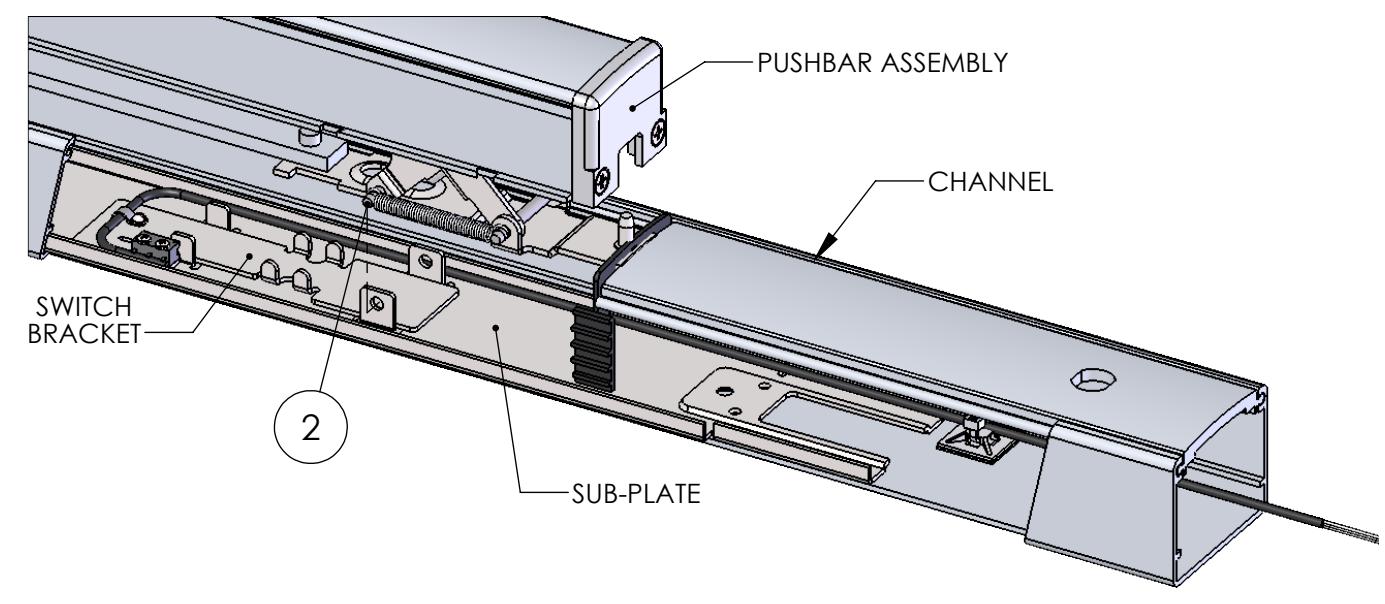
- 1. Separate the channel from the pushbar assembly.
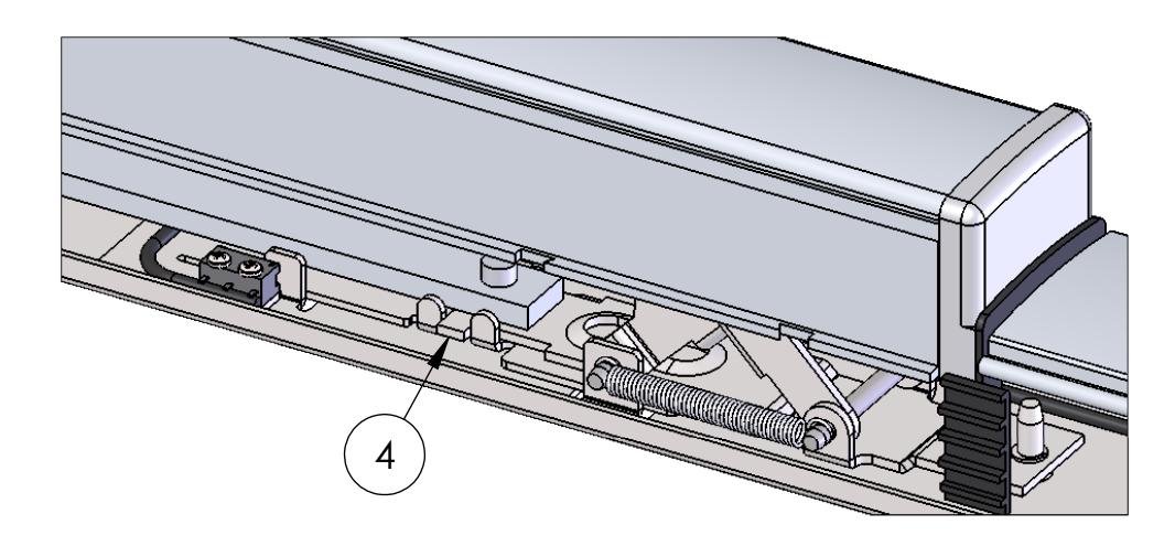
- 2. Remove the rear pin securing the pushbar assembly to the sub-plate and elevate the rear of the pushbar assembly.
- 3. Locate the K-129 Kit between the sub-plate and the pushbar assembly.
- 4. Lower the pushbar assembly back into position and replace the rear pin to secure the pushbar assembly to the sub-plate. Verify the tabs of the pushbar assembly linkage are between the tabs of the switch bracket.
- 5. Route the lead wires along the outside edge of the pushbar assembly.
- 6. Attach the channel to the pushbar assembly.
- 7. Secure the lead wires to the inside of the channel using the supplied ty-wrap mount and ty-wrap.