980S and 12-L980 Mullion Instruction Sheet
Open the original PDF document
View PDFINSTALLATION INSTRUCTIONS FOR L980S & 12-L980 STEEL MULLIONS

FOR ASSISTANCE CONTACT SARGENT AT 800-727-5477 or www.sargentlock.com
Tools Required:
- · Measuring Tape
- · Pencil
- · Drill & Tap Sizes: #7 drill and 1/4"-20 tap
- · Concrete Drill: 3/8" diameter
- · Center Punch
- · Hammer
- · #3 Phillips Screw Drivers
- · 5/64" Allen Wrench
- · 1/8" Allen Wrench
To install mullion in frame
- 1. Close and block the doors against the frame stops. Check gap between door leaves and door to frame and correct if necessary.
-
2. Locate the center of the opening on the floor. Using the bottom retainer mark the positions for the two drop-in fasteners.
- a. The bottom of the door should come to rest against the surface of the mullion.
- b. Modify threshold as required.
- 3. Drill holes with 3/8" diameter cement bit to a minimum depth of 2-1/2".
- 4. Fasten bottom bracket to floor.
-
5. Locate the center of the opening on the top of the frame. Using the top retainer mark the positions for the four fasteners.
- a. The door should evenly rest against both the frame stop and the mullion.
- b. If a top retainer mounting kit is used, modify weather-stripping as required.
- 6. Drill and tap each location for 1/4"-20 fasteners.
- 7. Mount top retainer on frame with provided fasteners.
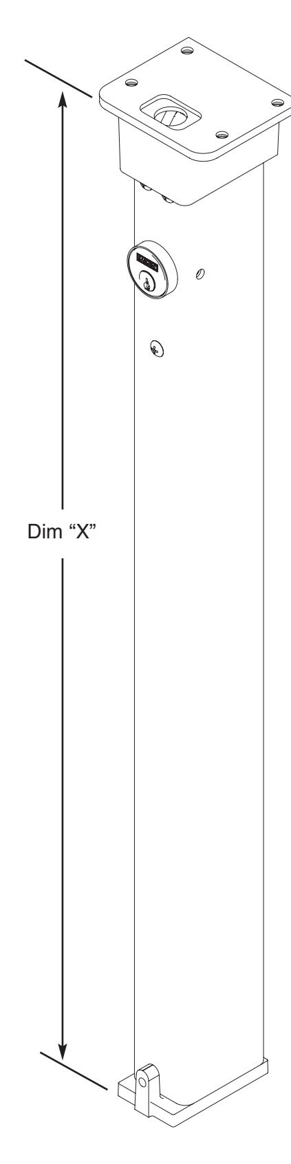
- 8. Measure "Dim X" as shown. Remove material from the bottom of the mullion per the formula: length of mullion = "Dim X" minus 3/4". Note –This leaves approximately 1/8" clearance between the mullion and the top bracket when mounted.
- 9. Place mullion onto bottom bracket and pivot into opening to latch.
- 10. Tighten bottom bracket set screw to prevent mullion rattle.
- 11. Install exit devices according to manufacturer's instructions.
ASSEMBLY INSTRUCTIONS FOR L980S & 12-L980 STEEL MULLIONS
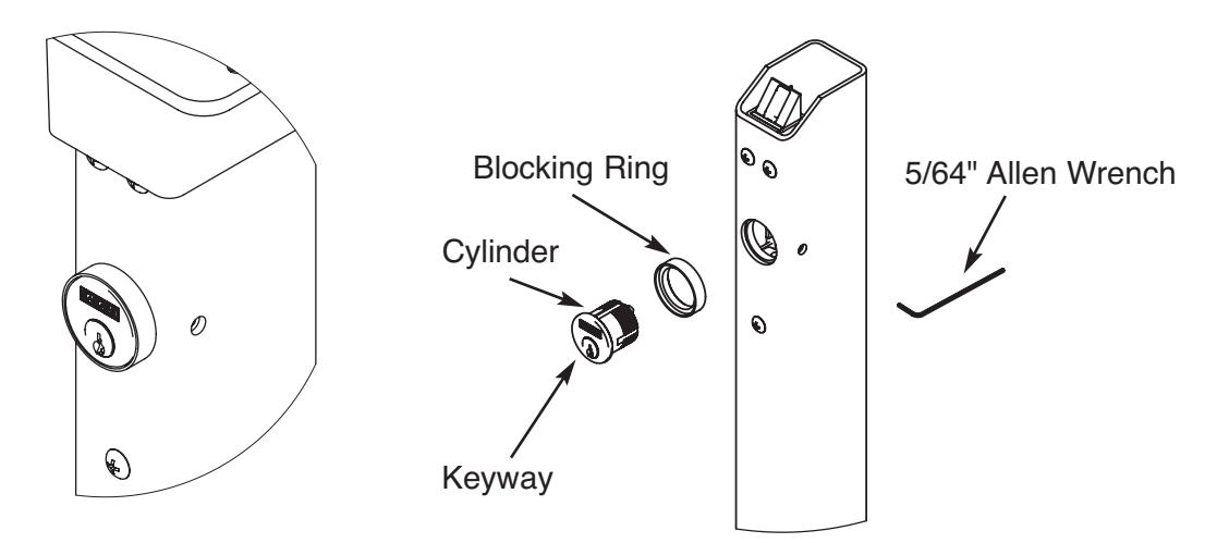
Installation of Cylinder
Installation of cylinder:
- 1. Depress latchbolt and hold fully retracted.
- 2. Carefully thread cylinder with blocking ring into lock assembly until it bottoms out.
- 3. Unscrew the cylinder orienting keyway at bottom.
- 4. Release latch bolt. Note: If latch bolt is not fully projected loosen cylinder an additional 1-2 full turns.
- 5. Tighten set screw with 5/64" Allen Wrench through access hole in side of mullion.
- 6. Check operation of cylinder and lock assembly. Note: Key only turns counter-clockwise.