9706, 10, 13, 15 Vertical Rod Exit Device Installation Instructions
Open the original PDF document
View PDFInstructions for installing the 9700/12-9700 Surface Vertical Rod Exit Device
FOR ASSISTANCE, CALL SARGENT AT 1-800-727-5477 or www.sargentlock.com
CAUTION: CHECK BEFORE STARTING DOOR PREP Door should be fitted and hung. Check box label for size of exit device, function, hand and design.
Surface of the door must be flush. Clear away any raised projections to allow exit device to rest on flat surface of the door.
THIS EXIT DEVICE IS NON-HANDED
Right hand reverse bevel OUT
Tools required
- 1. Measuring tape
- 2. Power drill
- 3. Drill bits: 3/32", 1/4", 11/32", 3/8", #25
- 4. Taps: #10-24
- 5. Screwdrivers: Phillips #2 and #3
*NOTE: 12-9700 shown
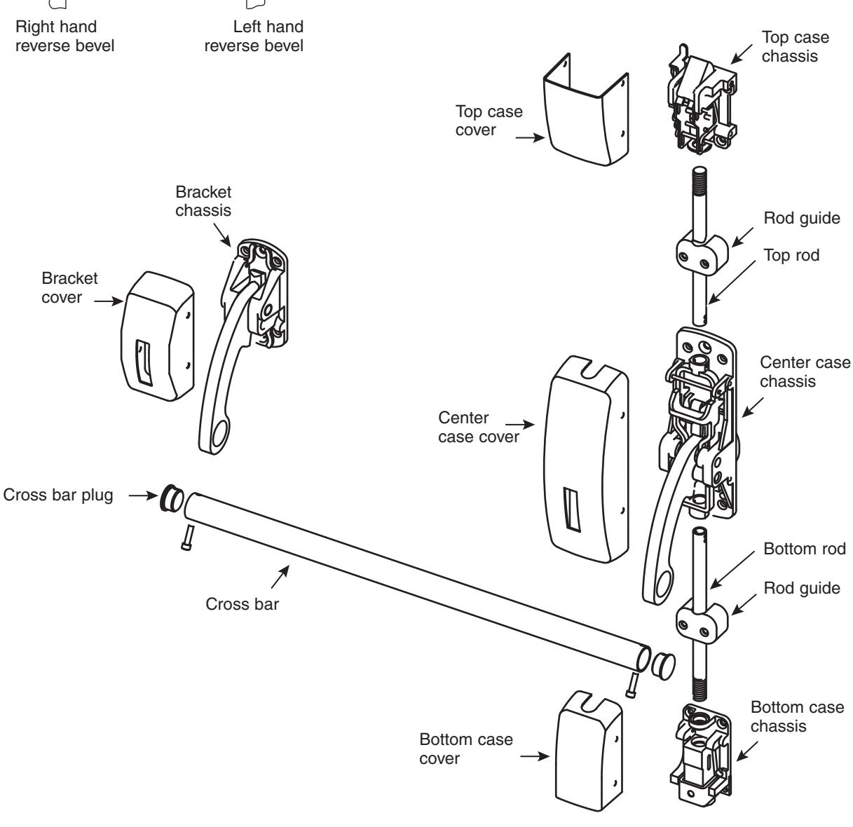
9700/12-9700 Vertical Rod Exit Device
All 9700/12-9700 Exit Devices are not handed and can be used on either hand door.
NOTE: Trim may or may not be handed
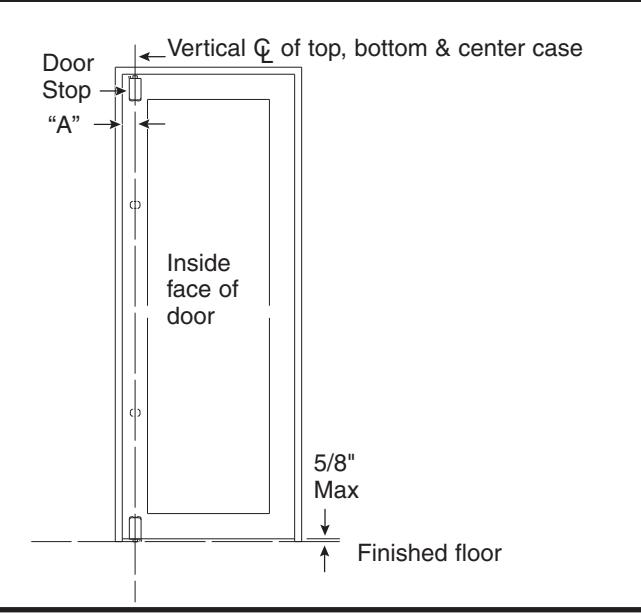
Mark vertical centerline on inside of door as follows:
A. Where the lock stile is approx. 4-1/2" wide or wider - "A" = 2-3/4"
1
B. On single doors where the width of lock stile is under 4-1/2", make "A" equal to 1/2 the width of the exposed lock stile (when door is closed against stop)
2 Locate and place templates as follows:
- A. With door closed, tape top case template to inside of door along reference lines marked in step 1
- B. Tape center case template to door in the same manor (see dimension on template to obtain correct height from finished floor)
- C. Using cross bar hole centers for measuring, locate vertical center line of bracket (See dimensions on template to obtain correct height from finished floor)
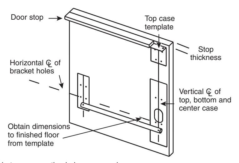
Locate templates between mounting holes on cross bar
3 Drill and cut holes as directed on template
4 Attach outside trim when used
- A. Some outside trims are through-bolted to the center case. Trims of this type must be put on in conjunction with step 5. Check outside trim used
- B. Check for correct spindle or thumb-piece length
- C. Install key cylinder (check for correct tail piece length)
9700/12-9700 Vertical Rod Exit Device
SARGENT ASSA ABLOY
5
Remove cover from center case chassis and mount chassis on door. Using (4) 10-24 flat head machine screws or (4) # 10 flat head wood screws
IMPORTANT! On (12) 9706, (12) 9762, (12) 9713 and (12) 9763 functions, make sure key cylinder hub in chassis is turned to correct position before mounting chassis on door.
NOTE: (12) 9713 and (12) 9706 does not have this hub assembly when used with ET Trim.
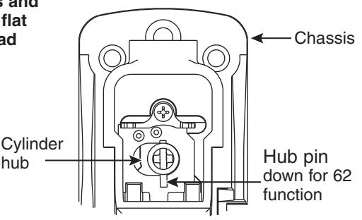
For (12) 9762/(12) 9706 long end of pin faces down. Cylinder turns 180° in both directions.
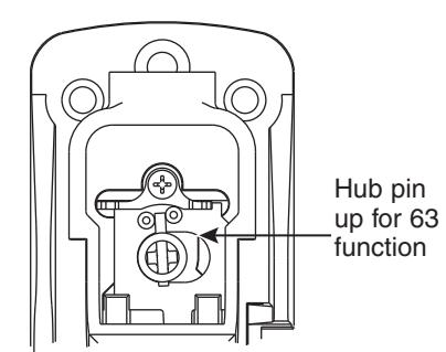
For (12) 9763/(12) 9713 long end of pin faces up. Cylinder turns 360° to the left or right.
6
Mount bracket chassis on door using (4) 10-24 flat head machine screws or (4) #10 flat head wood screws and attach bracket cover to chassis using (4) 8-32 oval head machine screws
Mount top strike in position prepped in step 2
Tighten screws securely.
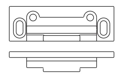
649 Standard strike for both 12- Fire rated and standard top case
- (2) 10-24 round head machine screws
- (2) 10-24 oval head machine screws
8
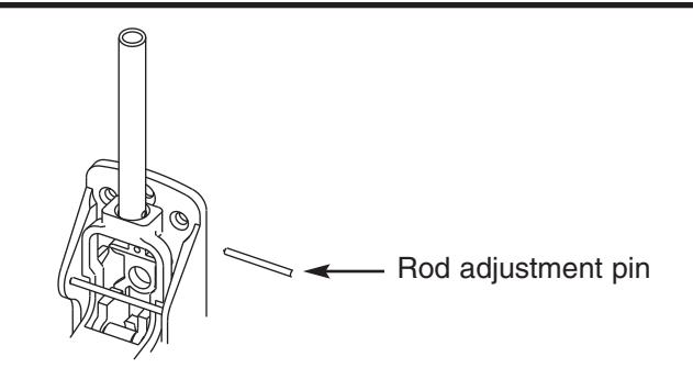
Mount top case and rod
- A. Make sure crossbar arm is not in lockdown position
- B. Screw top rod into top case until finger tight
- C. Slide top rod into main slide do not pin in place
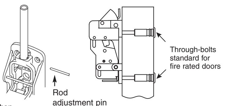
- D. Attach top case at location prepped in step 2; Note: Through-bolts required and supplied for Fire Rated Top Case on wood doors
- E. Unscrew top rod until top hole in rod is aligned with hole in main slide and insert rod adjustment pin
NOTE: 12 - Top case shown
NOTE: Use two (2) #10 steel screws and mortise nuts (when provided) in the position illustrated in the top and bottom chassis. Steel mortise nuts are twin knurled for identification.
9700/12-9700 Vertical Rod Exit Device
9 Mount bottom rod assembly in the same manner as the top rod assembly and fasten bottom case chassis
- 1. Verify rail is not dogged
- 2. Screw rod into bottom case until finger tight
- 3. Slide bottom rod into main slide
- 4. Insert adjustment pin into middle hole
- 5. Position bottom case on door, centered on vertical reference line. Raise or lower to achieve gap indicated for strike application (see drawings below).
- 6. Drill and tap mounting holes
- 7. Mount bottom case Tighten fasteners securely
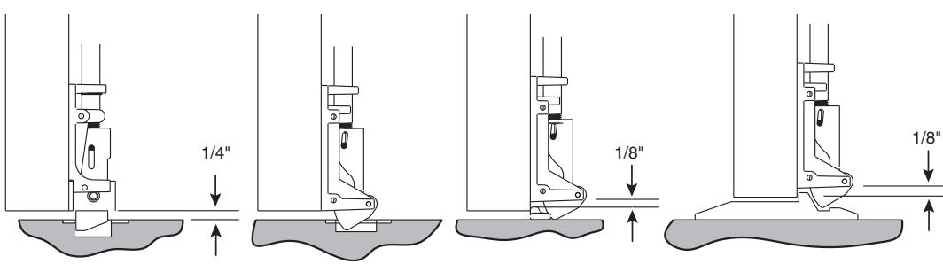
Mortise applied strikes Surface applied
strike
Latch track thresholds (by others)
10 Bottom Strikes
Mark and install according to appropriate template and following notes
For surface applied strikes: 624, 647
- 1. Transfer vertical centerline to floor or threshold and mark
- 2. Center strike on line marked
- 3. Mark mounting holes
- 4. Drill holes for required fasteners
- 5. Mount strike with fasteners provided
- 6. Tighten screws securely
For mortised strike: 655 follow steps in section 9 above. Mark mounting holes and outline of strike.
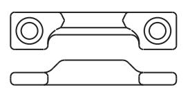
624 Standard strike
- (2) 12-24 flat head machine screws
- (2) #12 flat head wood screws
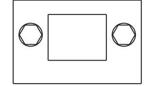
655 12-Standard fire rated strike (2) 1/4- 20 flat head machine screw
647 14-Standard strike (2) # 12 flat head wood screws
Adjustment 11
- A. Fine adjustment is made by turning rod into case to shorten or out of case to lengthen
- B. Rough adjustment is made by changing hole used for adjustment pin
-
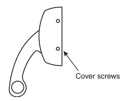
• Apply covers using 8-32 oval under cut hard machine screws
12
- • Attach guides using #10 Oval Head Screws, rods must move freely with guides
- Slide crossbar into chassis and bracket arms and attach crossbar plugs to crossbar using socket head cap screws 13