939310 COR42-COR52-COR60 Surface Mounted Door Coordinator Template
Open the original PDF document
View PDFCOR42-COR52-COR60 SURFACE MOUNTED COORDINATORS
FOR METAL AND WOOD DOOR APPLICATIONS
INSTALLATION INSTRUCTIONS FOR SURFACE MOUNTED COORDINATORS
NOT TO SCALE
12-31-14
TEMPLATE: 939310
REV. 0
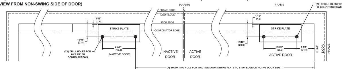
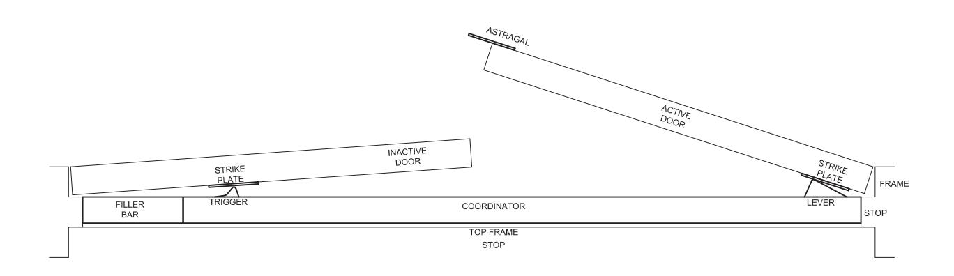
1. CLOSE DOORS AGAINST STOP. LOCATE AND INSTALL STRIKE PLATES FOR INACTIVE AND ACTIVE DOORS (FIG.1).
(FIG.1) INACTIVE DOOR STRIKE PLATE AND ACTIVE DOOR STRIKE PLATE (RH/LHR SHOWN)
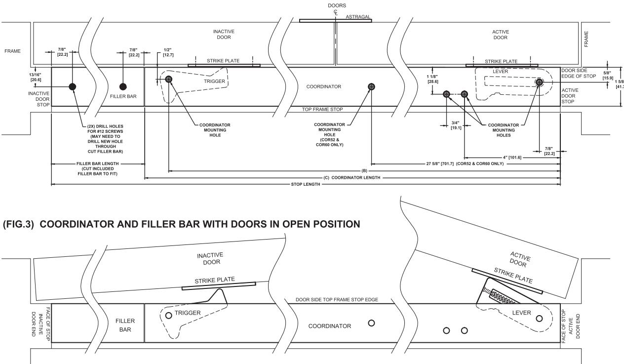
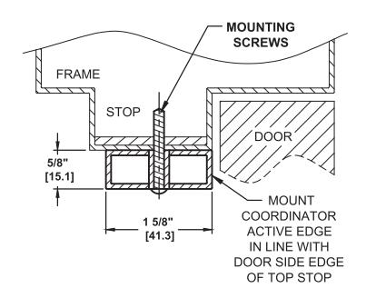
2. LOCATE COORDINATOR IN LINE WITH DOOR SIDE AND ACTIVE DOOR END OF TOP FRAME STOP (FIG.2). DRILL ONE MOUNTING HOLE WITH A #10 DRILL.
INSTALL #12-24 THREAD-FORMING SCREW (SEE FIG.4 FIG.5, PAGE 2) TO HOLD THE COORDINATOR IN POSITION BEFORE DRILLING ADDITIONAL MOUNTING HOLES (FIG.2).
3. INSTALL FILLER BAR TO COMPLETELY FILL THE OPENING BETWEEN THE END OF THE COORDINATOR AND FACE OF INACTIVE DOOR STOP (FIG.2 & FIG.3). FILLER BAR MAY NEED TO BE CUT TO FIT DIFFERENT SIZE DOOR OPENINGS.
| L | MODEL# | (A) | (B) | (C) |
| Γ | COR42 | 37-1/2" | 41" | 42" |
| [952.5] | [1041.4] | [1066.8] | ||
| ſ | COR52 | 47-1/2" | 51" | 52" |
| [1206.5] | [1295.4] | [1320.8] | ||
| ſ | COR60 | 55-1/2" | 59" | 60" |
| [1409.7] | [1498.6] | [1524.0] |
- (A) = ACTIVE DOOR STRIKE PLATE (B) = COORDINATOR MOUNTING HOLE (INACTIVE DOOR SIDE)
- (INACTIVE DOOR SIDE) (C) = LENGTH OF COORDINATOR
(FIG.2) COORDINATOR AND FILLER BAR WITH DOORS IN CLOSED POSITION
NOTES:
- 1. INSTALL COORDINATOR BEFORE ANY OTHER HARDWARE, EXCEPT HINGES.
- 2. DIMENSIONS IN [MM]
- 3. ALWAYS CHECK PDQ WEBSITE FOR THE MOST RECENT TEMPLATE REVISION AT WWW.PDQLOCKS.COM
PAGE 1 OF 2
PDQ Manufacturing 2754 Creek Hill Rd. Leola, PA 17540 800-441-9692 Fax: 717-656-6892 www.pdqlocks.com
TEMPLATE: 939310 REV. 0 12-31-14
NOT TO SCALE
(FIG.4) DOOR IN CLOSED POSITION
(FIG.5) DOOR IN OPEN POSITION WITH LEVER AND TRIGGER PROJECTION
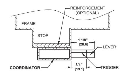
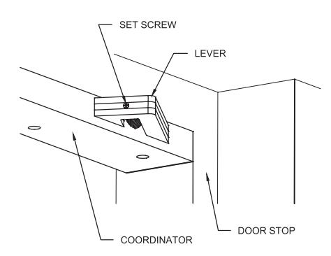
(FIG.6) LEVER SPRING TENSION ADJUSTMENT
FIELD ADJUSTMENT OF COORDINATOR OVERRIDE:
FIELD ADJUSTMENT OF DOOR CLOSERS IS REQUIRED AFTER INSTLLATION OF COORDINATOR TO INSURE AGAINST DOORS CLOSING TOO FAST AND CHANGING COORDINATOR MECHANISM.
WITH SOME DOORS THE ACTIVE DOOR WILL OVERRIDE THE LEVER BEFORE THE TRIGGER IS DEPRESSED. THE LEVER SPRING TENSION MUST BE INCREASED.
USE A PHILIPS HEAD SCREWDRIVER TO INCREASE THE LEVER SPRING TENSION BY TURNING THE SET SCREW AT THE END OF THE LEVER CLOCKWISE FOR HEAVY DOORS (FIG.6).
ADDITIONAL HARDWARE MAY BE REQUIRED:
1. STOP APPLIED HARDWARE MOUNTING BRACKETS: In some situations, where hardware such as parallel arm door closers or surface vertical rod strikes would normally be mounted to the door stop, installation becomes a little more complicated because the Coordinator mounted directly onto the stop will cover the stop and no holes can be drilled into the Coordinator (they would interfere with the Coordinator mechanism).
The mounting brackets MB03 (for stop widths 7/8" to 2-1/4") and MB02 (for stop widths over 2-1/4") are installed over the Coordinator and mounted to the door frame. The coordinator is then installed by drilling and tapping holes into the brackets.
When mounting brackets are used, be sure to lower mounting holes for any door applied hardware by 15/16" to allow for the Coordinator and mounting brackets. The mounting bracket type and quantity need to be ordered with the coordinator.
2. 910 CARRY BAR: This item can be supplied in situations which allow the inactive door to open before the active door. The carry bar will throw the active door open, and allow the coordinator to engage both doors, and coordinate them to close correctly. The carry bar is not needed when the inactive door is equipped with flush bolts.
PAGE 2 OF 2
D)(0
PDQ Manufacturing 2754 Creek Hill Rd. Leola, PA 17540 800-441-9692 Fax: 717-656-6892 www.pdqlocks.com