923 Series Keypad Installation Instructions – Purchased before June 2021
Open the original PDF document
View PDF

801 Avenida Acaso, Camarillo, Ca. 93012 a (805) 494-0622 www.sdcsecurity.com a E-mail.'service@sdcsecurity.com
INST ALLATION INSTRUCTIONS 923 EntryCheck TM
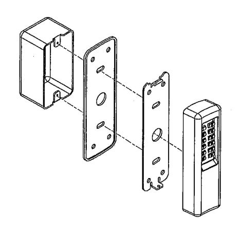
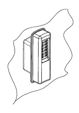
The 923 Indoor/Outdoor Keypad Surface Mount EntryCheckTM is a digital keyless entry system designed for access control applications. The keypad is integrated in a heavy cast vandal resistant housing, designed to be mounted on a rugged, surface mounting plate and may be mounted in a standard single-gang electrical box. The indoor/outdoor backlit keys have bright, easy-to-read graphics.
Up to 500 entry codes, from I to 6 digits in length, can be programmed. They can activate either, or both of the relay outputs. The "anti-passback" feature prevents using the same code again before the programmed time elapses.
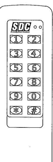
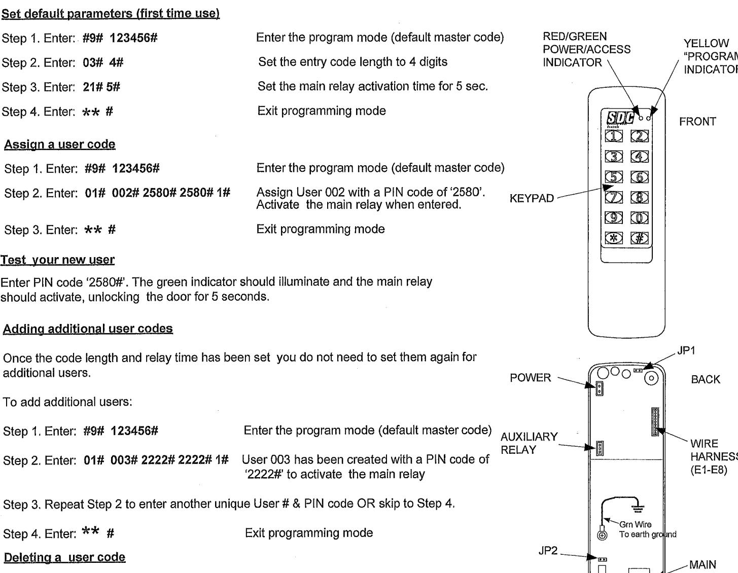
All system indicators are long-lasting, solid state LEDs. Two indicators show the status of the entry system. The left indicator lights red to indicate power, then turns green when access is granted. The right yellow LED flashes when the keypad is in programming mode. An internal sounder beeps when each key is pressed. An internal jumper sets the sounder volume high or low
The SENSE input can be used two ways. If programmed for "door sense" the input is wired to a normally closed switch on the door to detect when the door is opened or closed. Forced entry or door ajar situations can then be detected. Using door sense, the "Auto-relock" feature will prevent "tailgating" by turning off the Main Relay output immediately when the door is closed after access has been granted. If the SENSE input is programmed for "inhibit", the input can be wired to a "service" switch or automatic timer that will disable the Main Relay when required.
The REQUEST-TO-EXIT input can be wired to a pushbutton to provide codeless activation of Main Relay, Auxiliary Relay, Output #3 or Output #4 (programmable).
The ALARM SHUNT output activates when access is granted. This output can be wired to shunt alarm contacts on the access door/gate to prevent triggering of an alarm when authorized access occurs.
The 923 EntryCheckTM is powered from a 12 or 24V AC or DC source. 7he EEPROM memory retains all entry codes and programming, even without power. An internal jumper is provided to reset the master code. The Main Relay has a 5 Amp capacity. The Auxiliary Relay has a 2 Amp capacity. Two solid state outputs, capable of switching 100 mA to common, are programmable to signal forced entry, door ajar, lockout, alarm circuit shunting, request-to-exit, and keypad active conditions.
Features
- Keypad programmable
- 500 user codes
- 4 to 6 digit user codes
- 4 independent outputs
- 4 independent timers
- 2 Form C relay contacts
- 2 solid state open collector outputs
- Program entry codes to activate one or two relays
- Disable input
- Door sense input
- Request-to-exit/enter input
- Keypad tamper lockout
- Timed anti-passback
- Anti-tailgate
- Two LED status indicators
- Tactile key feel
- Audible code entry verification
- 12 or 24V, AC or DC operation
SPECIFICATIONS
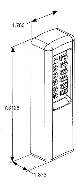
Mechanical
Dimensions: 1.750" Wx 7.3"l25" H x 1.375" D (1.4375" wall projection)
Electrical
Input Voltage: 12/24 Volts AC or DC
Operating Current: 30 mA typical, 150 mA max
Output Ratings
Main Relay: Form"C" 5 Amps @ 28 Volts max Auxiliary Relay: Form "C" 2 Amp @ 28 Volts max Type: Solid state outputs (Outputs #3 & #4) Short-to-common100 mA @ 24 VDC maximum
Environmental
Temperature: -4oF to 140oF (-20oC to 60oC) Humidity: 5% to 95% non-condensing
QuickStart Proqramminq
Step 4. Enter: #9# 123456# Step 2. Enter: 02# 002# 002#
Step 3. Enter: ** #
You must first enter programming mode to perform any function. The yellow indicator will blink slowly showing that the 923 EntryCheckTM is in programming mode. Use the option codes to program each function. After the new data entry is complete for each function, the yellow indicator will flash quickly while the data is being stored and the green indicator will light briefly if the programming has been accepterJ. The red indicator will light if any programming data is entered incorrectly or the function is rejected. If a red indicator is seen, the entire function (option code + data) will have to be fully re-entered.The keypad will remain in programming mode until ** # is pressed or affer 30 seconds ofinactivity.
Set default parameters (first time use)

IF THE UNIT IS AC POWERED, MAKE SURE THAT THE SECONDARY OF THE SYSTEM IS ISOLATED FROM EARTH GROUND
RELAY
KEYPAD WIRING
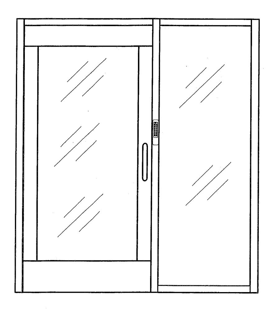
See Fig. 3 for an example of a basic door installation. The keypad is mounted adjacent to the door. An electric door strike is mounted in the door jamb to release the door lock. A door contact switch is mounted on top of the door jamb for detecting when the door is open.
Use the following steps to wire the keypad. Refer to the wiring diagram shown in Fig. 4 to assist in the wiring.
Note: For lock power, use 18 AWG wire or larger (depending on load). Use 22 AWG or larger for signal connections. Refer to lock manufacturer's documentation for lock power requirements.
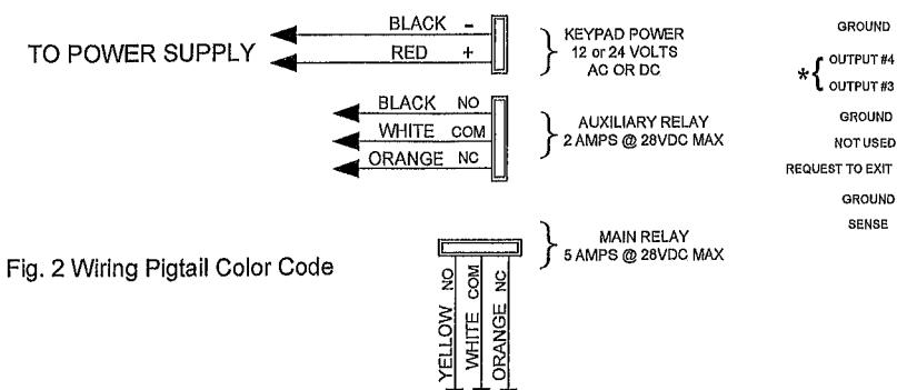
Output Connection
Install a low-voltage fail-secure electric door strike at the door to be controlled. Route 2 wires from the door strike to the keypad. Connect an MOV across the coil wires of the strike. Connect the (+) door strike wire to the keypad's MAIN RELAY N.O wire (yellow). Connect the other door strike wire to the keypad's PWR(-) wire (black). Connect the keypad's MAIN RELAY COM wire (white) to the keypad's PWR(+) wire (red) .
Power Connection
Connect the power supply's output terminals to the keypad's PWR(+) wire (red) and PWR(-) wire (black). If using a DC supply, observe wiring polarity. If an AC transformer is being used, polarity does not mater.
Caution: If the unit is AC powered, make sure the secondary of the system transformer is <u>isolated</u> from earth ground.
Earth Ground
To avoid damage to the unit from static discharges, this unit must be connected to a proper earth ground. Connect the green earth ground wire to a good earth grounding point. Suggested wiring size is 18 AWG for

Sense Input
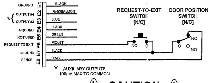
RE Note: The SENSE input (gray wire) can be programmed as either a door sense or inhibit input. <u>Both features cannot be used at the same time</u>. If you are not using the sense input, program this input for inhibit.
Door Sense: (Detect forced entry or door ajar conditions) Install a normally closed door switch on the door and route two wires from the switch to the keypad. Connect the door switch to the keypad's SENSE wire (gray/ E8) and COM wire (any black wire).
Inhibit: (Disable access) If an inhibit switch or timer is going to be used for temporarily disabling the keypad, route two wires from the switch or timer to the keypad. Connect the inhibit switch/timer's normally open contacts to the keypad's SENSE (gray/ E8) and COM (black wires) terminal.
Request-to-Exit Input (wiring shown on page 3, fig. 4)
If a request-to-exit pushbutton is going to be used, route two wires from the keypad box to a normally open pushbutton mounted on the secure side of the door. Connect the wires to the pushbutton and to the keypad's REX wire (violet/ E6) and COM (black wires) terminals.
Solid State Outputs
The two solid state outputs (Outputs #3 & #4) can be programmed to activate during various conditions. These "open collector" outputs can be used to activate indicators or sounders. See fig. 5 for wiring examples using the solid state outputs.
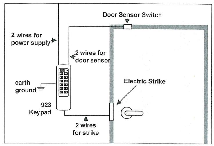
Fig. 3 Basic Door Installation
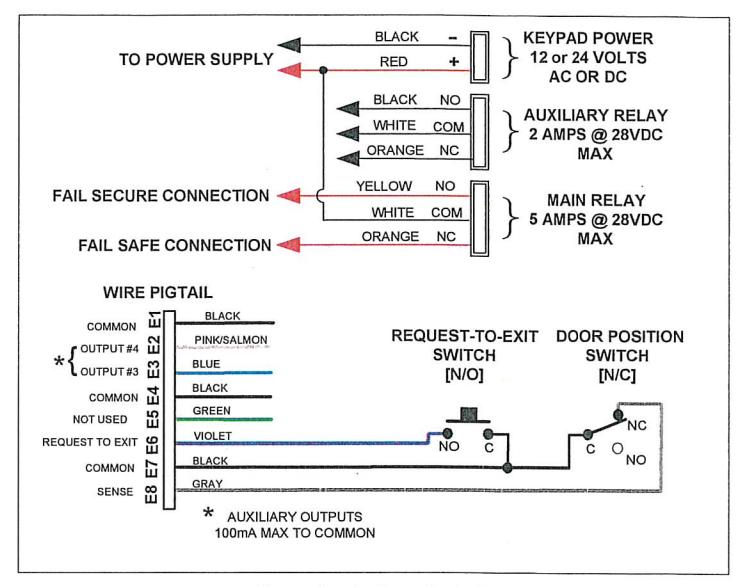
Fig. 4 Basic Door Installation Wiring
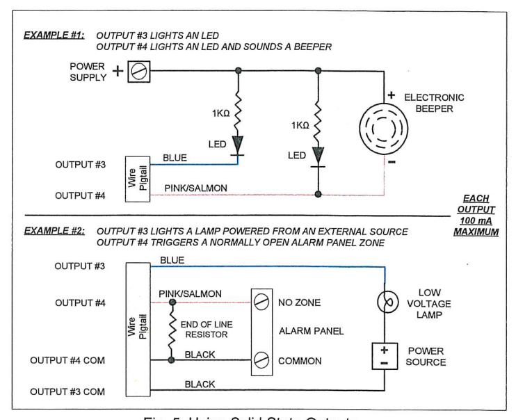
Fig. 5 Using Solid State Outputs
FACTORY DEFAUITS
|
Master
Programming Code |
123456 |
|---|---|
|
Entry
Code Length |
,,,4 digits |
|
Request-to-exit
Output Relay |
No
Output |
|
Alarm
Shunt Output |
Disabled |
|
Forced
Entry Output |
.No Output |
|
Door Ajar
Output |
No Output |
|
Main
Relay On Time |
.02 Seconds |
|
Auxiliary
Relay On Time |
.02 Seconds |
|
Solid
State Output #3 0n Time |
o:
Seconds |
|
Solid
State Output #4 0n Time |
.02 Seconds |
|
Door
Sense/Inhibit Input |
.Door
Sense |
|
Keypad
Lockout Output |
.Disabled |
|
Keypad
Active Output |
.Disabled |
|
Beeper
Sounds When Key Pressed |
.Yes |
|
Beeper
Sounds During Relay #'l |
.No |
|
Beeper
Sounds During Relay #2 |
.No |
|
Beeper
Sounds During Output #3 |
.No |
|
Beeper
Sounds During Output #4 |
.No |
|
Keypad
Lockout Count |
.3 Tries
Before Lockout |
|
Anti-Passback
Time |
.No Anti-Passback |
| Auto-Relock | .0n |
BASIC PROGRAMMING
When the 923 EntryCheckTM is in Programming Mode the yellow indicator will blink slowly. After a programming command is selected, the yellow indicator will flash rapidly while the keypad is waiting for user input data. The green indicator will light if the data is accepted. The red indicator will light if any programming data is entered incorrectly, and the command will have to be fully reentered. IMPORTANT!: Codes are stored by User #. It is imperative that the User numbers and their assigned personnel are managed in the event a specific user ever needs to be deleted.
Enterinq Programming Mode
The 6-digit Master Programming Code (default = 123456) is used to enter Programming Mode.
Press: # 9 # Master Code #
Master Code = the current 6-digit Master Programming Code
Exitinq Proqramminq Mode
Press: **#
The red indicator will light after exiting Programming Mode
hk>te: The 923 will automatically exit Programming Mode after 30 seconds of inactivity
Re-entering a Command After a Mistake
If the red indicator lights, signaling an incorrect entry, or an incorrect key is pressed during programming, to clear the keypad and re-enter the command:
Press: * 9 #
Settinq Entry Code Lenqth Default:4 diqits
Press: 0 3 # Length #
Length = 4-6 for entry code length
Note: If the Entry Code Length is going to be changed from the factory default of 4 digits, make this change first before programming any entty codes.
Addinq a New Entry Code
Press: 01 # User # Code # Code # Relay #
User = User number to be added (00al-500). Must be unique. Code=The new entry code: 1-999999, depending on code length Relay-Relay output entry code will activate:
1 =Main Relay 2=Auxiliary Relay 3=Both Relays
10=Relay #7, toggled 20=Relay#2, toggled 30=both Relays toggled l2=Relay #1 toggled; Relay #2 timed open
21 =Relay #1 timed open; Relay #2 toggled
The yellow indicator will flash quickly while the 923 stores the new user information in memory The green indicator will light when the new user is accepted. If the user number already exists or an entry error has been made, the red indicator will light. Delete the user and re-enter the new information again.
Note: Leading zeros (zeros before the Code number, i.e.OOOl) do not need to be entered when programming a new code. The 923 will internally add any zems fo fill digits determined by the entry code length setting. Leading zems will have to be entered by the user when entering their code to gain access.
Chanqing a User PIN
Press: 04 # User# New Code # New Code # User =The user number whose PIN will be changed
Erasinq a Single Entiy Code
Press: 0 2 # User # User #
User=The userlD to delete
The yellow indicator will flash quickly while the 923 searches its memog for the Llser to erase. The green indicator will light when the code is erased.
Erasinq All Users
WARNING: PERFORMING TH/S COMMAND WILL REMOVE USERS FROM THE MEMORY
Press:9 7 # 0 0 0 0 0 0 # 0 0 0 0 0 0 #
Note: The green indicator will light while the memory is being erased. This may take up to 15 seconds.
PROGRAMMING OPTIONS
There are several 923 EntryCheckTM programming options. For most installations, the factory set default options are sufficient. The keypad must be in Programming Mode to make these changes.
Proqramminq the 923 To Hold the Output
SDC's EntryCheckTM products have a programmable "Toggle Mode" available for each relay and solid-state output. When an output is programmed for Toggle Mode, the output alternates from OFF to ON or from ON to OFF each time it is activated. When output is toggled on, the green LED remains solid until toggled off.
The rules for a toggle output are:
- * If the output is OFF, it will tum ON and stay on until the next activation.
- If the output is ON, it will tum OFF and stay off until the next activation.
- An authorized PIN, Card, orREXinputprogrammed to momentarily activate that same relay will reset the relay to its normal state.
(Typical Programming cant.)
See the following example that sets entry codes 1234 for normal and 5678 for toggle operation.
Press: 01 # 1 2 3 4 # 12 3 4 # 1 #
Ol=Programming Step; l234=Entry Code; l=Main Relay
Press: 01 # 5 6 7 8 # 5 6 7 8 # 20 #
Ol=ProgrammingStep; 5678=EnttyCode; 20=AuxiliaryRelay
toggle
Select Door Sense or l Default: INHIBIT
The Sense Input (gray wire) can be programmed for either DOOR SENSE or INHIBIT.
Press: 10 # Jnput #
Input=O forDoor Sense; =1 for Inhibit
When programmed for DOOR SENSE, if an open condition on the input occurs before access is granted (with an entry code or with the request-to-enter input) a FORCED ENTRY output will occur. If an open condition remains 60 seconds affer a relay activation for access, a DOOR AJAR output will occur. NOTE: Function 1l and/or 12 must also be enabled to use Door Sense.
When programmed for INHIBIT, a closed condition on the input will prevent Relay #1 from activating when access is requested with an entry code. This mode is typically used with an external timer to disable the access device at certain times.
Select Forged Entry Output Default: No Output
Sets which output activates if the DOOR SENSE input opens before access is granted. This output is timed and configured by the relay "On-time".
Press: 1l # Output #
Output-Output to Activate(0-4)
1=MainRelay; 2=AuxiliaryRelay; 3=Output#3; 4=Output#4; 0=No Output
Select Door Ajar Output Default: No Output
Sets which output activates if the DOOR SENSE input stays open 60 seconds after access is granted (door ajar time is adjustable using Function 25). This output is not timed.
Press: 12 # Output #
Output=Output to Activate (0-4) l=MainRelay; 2=AuxiliaryRelay; 3=Output#3; 4=Output#4; 0=No Output
Select Keypad Lockout Output Default: No Output
Sets which output activates when the keypad is "locked out" after too many incorrect entry code attempts. The lockout time is 60 seconds.
Press: 13 # Output #
Output-Output to Activate (0-4)
I=Main Relay; 2 = Auxiliary Relay; 3=Output #3; 4=Output #4; 0=No Output
Select Keypad Active Output Default: No Output
Sets which output activates when any keys are pressed. This output is timed. If toggle mode is selected for the output, the timer value defaults to 2 seconds.
Press: 14 # Output #
Output=Output to Activate(0-4)
j=MainRelay; 2=AuxiliaryRelay; 3=Output#3; 4=Output#4; 0=No Output
Select Alarm Shunt Output Default: No Output
Sets which output activates during the time access is granted. (Use this output ot shunt alarm contacts attached to the access door.) This output may be timed or toggled.
Press: 15 # Output #
Output-Output to Activate(0-4)
l=MainRelay; 2=AuxiliaryRelay; 3=Output#3,' 4=Output#4; 0=No Output
Select Request-to-Exit Output Default: No Output
Sets which output activates when the Request-to-Exit input is grounded. This output may be timed or toggled.
Press: 18 # Output #
Output=Output to Activate(0-4)
1=MainRelay; 2=AuxiliaryRelay,' 3=Output#3; 4=Output#4; 0=No Output
REX input terminates toggle of Main or Aux. Relay
Anti-Tamper Output Default: No Output
Sets which output activates when the Anti Tamper switch on the back or the keypad is activated.
Press: 17 # Output #
Output-Output to Activate(0-4)
0=No Output; 2=Auxiliary Relay; 3=Output #3; 4=Output #4;
Mpin Relay On-time Default: 02 Seconds
Sets the length of time the Main Relay activates when triggered. Green LED is on when Main Relay is active.
Press:21 # Seconds #
Seconds=Output time in seconds (0-60)
Auxiliary Relay On-time Default: 02 Seconds
Sets the length of time the Auxiliary Relay activates when triggered.
Press: 2 2 # Seconds #
Seconds=Output time in seconds (0-60)
Solid-state Output #3 0n-time Default: 02 Seconds Keypad Lockout C(+unt Default: 3 Tries
Sets the length of time Output #3 activates when triggered.
Press: 2 3 # Seconds #
Seconds=Output time in seconds (0-60), 99=Toggle Mode
Solid-state Output #4 0n-time Default: 02 Seconds
Sets the length of time Output #4 activates when triggered.
Press: 2 4 # Seconds #
Seconds=Output time in seconds (0-60), 99=Toggle Mode
Door Ajar Timer Default: 60 Seconds
Sets the amount of time the door may be held open afker an authorized access. The DOOR AJAR output will activate affer the time expires.
Press: 25 # Seconds #
Seconds=Held open time in seconds (1-60)
Beep Sounds on Keystrokes Default: Yes
Selects whether or not the keypad beeps as each key is pressed.
Press:4 0 # Sound # Sound=1 for Yes, =O forNo
Beep Sounds Durinq Main Relay Default: No
Selects whether or not the keypad beeps during Main Relay activation.
Press:41 # Sound # Sound=l for Yes, =O for No
Beep Sounds Durinq Auxiliary Relay Default: No
Selects whether or not the keypad beeps during Auxiliary Relay activation.
Press:4 2 # Sound # Sound=l for Yes, =O for No
Beep Sounds Durinq Output #3 Default: No
Selects whether or not the keypad beeps during Output #3 activation.
Press:4 3 # Sound # Sound=1 for Yes, =O for No
Beep Sounds Durinq Output #4 Default: No
Selects whether or not the keypad beeps during Output #4 activation.
Press:4 4 # Soiind # Sound'-1 for Yes, =O for No
Sets the number or incorrect entry code attempts allowed before the keypad 'Jocks out".
Press: 5 0 # Attempts #
Attempts=Number of attempts before lockout (2-7)
Anti-Pass Back Time Default: No Anti-Pass Back
Sets the length of time an entry code will not function after it is used.
Press: 51 # Minutes #
Minutes=Time in minutes (1-4), O=No Anti-passback
Selects mode for Keypad LED Backliqht Default: 30 Seconds
Selects whether or not the keypad back light stays OFF, lights for 30 seconds when activated or stays ON.
Press: 52 # Output #
0 = Light always OFF j = 30 sec light when activated (default) 2 = Light always ON
Chanqinq the Beeper Sound Level
The Keypad's beeper can be set to high or low level. Remove jumper JP1 to reduce beeper sound level.
Chanqinq the 6-Digit Master Programming Code
Press: 9 8 # Master Code # Master Code # Master Code=The new 6-digit Master Programming Code
| New | master | code: |
|---|
RESETTING KEYPAD
Master Reset
CAUTiON: Performing a master reset will clear the entire memory of the 923 and return a// programmable options to the factory default va/ues. ALL ENTRY CODES WILL BE ERASED. NOTE: The Master Code will NOT be reset.
- STEP 1 Disconnect power from the keypad.
- STEP 2 Press and hold down the " and # keys.
- STEP 3 Apply power to the keypad, continue holding the keys down until the red indicator starts flashing
- STEP 4 Release the keys. The red and yellow indicators will remain lit until the process is complete, then the yellow indicator will go out.
Resettinq the Master Code
- STEP I Remove the 923 from the wall and disconnect power from the keypad.
- STEP 2 Locate & Remove jumper at JP2. Reference page 2.
- STEP 3 Re-apply power. You will get a single beep and the yellow LED will flash momentarily.
- STEP 4 Replace jumper on JP2.
THE MASTER PROGRAMMING CODE IS NOW 123456.
MULLION MOUNT
WALL MOUNT