920PW Series Digital Keypad with Weigand and Prox Installation Instructions
Open the original PDF document
View PDF801 Avenida Acaso, Camarillo, Ca. 93012 • (805) 494-0622 • www.sdcsecurity.com • E-mail: service@sdcsecurity.com
INSTALLATION INSTRUCTIONS 920PW EntryCheck TM
The EntryCheck ™ 920PW indoor/outdoor Wiegand proximity reader with integral digital keypad is designed to interface with most Access Control Systems. It offers a 125KHz HID-compatible proximity reader with standard 26-bit Wiegand output. The built-in keypad may be programmed to output 26-bit Wiegand data, or a 4-bit word for high-security applications that require dual authentication (Card + PIN).
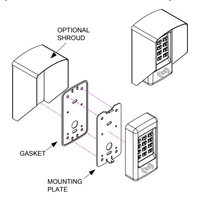
The backlit keys are bright and easy-to-read. A heavy cast, vandal resistant housing design with mounting plate allows the 920PW to be mounted on a rugged surface or on a standard single-gang electrical box.
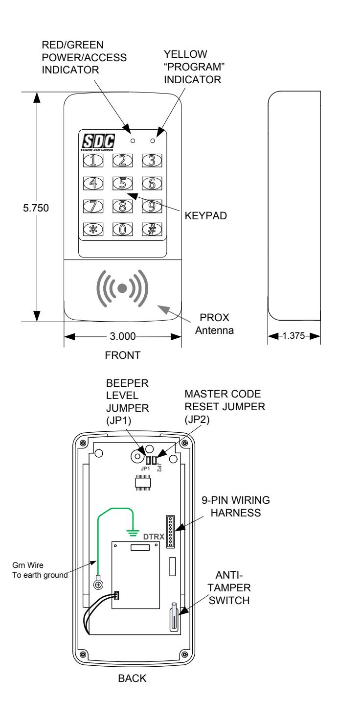
Two long lasting solid state LED indicators show the status of the system. The left bi-color indicator lights red to indicate power, or green to indicate an authorized access (controlled externally by host). The right indicator flashes yellow to indicate that the keypad is in programming mode.
Features
- 12 key illuminated 3x4 digital keypad with configurable illumination: always on, timed, off
- Supports HID (125KHz RFID) proximity protocols
- Suitable for Indoor/Outdoor use: Weather & vandal resistant
- Standard 26-bit Wiegand output for universal compatibility
- Programmable Site Code
-
Programmable Keypad Operation:
- 26-bit Wiegand, or
- 4-bit word
- Surface or single-gang mount
- Built-in tamper switch
- Two LED status indicators
- Audible annunciation of keystrokes with adjustable sound level: normal, low, off
- Tactile metal keys
- Includes wiring harness
- Optional privacy & rain shroud available
Specifications
- Operating Voltage: 5 16 Volts DC
- Current Consumption: 30mA (typical), 60 mA (max)
- Operating Temperature: -4° to 140°F (-20° to 60°C)
- Humidity: 5% to 95% non-condensing
- Dimensions (H x W x D): 5.75" x 3" x 1.375", (1.4375" wall projection)
- Housing: Weather-resistant cast metal
- Cabling: 6" wiring harness
- Reader Output: 26-bit Wiegand
- Keypad Output: 26-bit Wiegand or 4-bit word
- Max. Cable Distance to Host: 328ft (100m) @12VDC, 100ft (30m) @ 5VDC, using 18AWG cabling
-
Recommended Cable (shielded, multi-conductor) or equal:
- -Belden 5504FE (6 Cond)
- -Belden 5506FE (8 Cond, for Tamper Switch)
- Tamper switch: Form "C", 1A @ 30VDC
920PW WIRING & GROUNDING
See Fig. 3 for an example of a basic door installation. The 920PW is mounted adjacent to the door. An electric door strike is mounted in the door jamb to release the door lock. A magnetic switch is mounted on top of the door jamb for detecting when the door is open. The access host controller is located at a maximum distance of 300ft of the keypad reader, depending on the reader voltage provided.
Refer to the Fig. 4 or Fig. 5 for wiring details.
To avoid damage to the unit from static discharges, this unit must be connected to a proper earth ground. Connect the green earth ground wire to a good earth grounding point. Suggested wiring size is 18 AWG for earth ground.
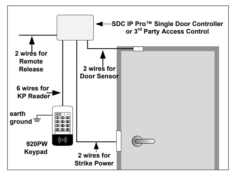
Fig. 3 Basic Door Installation
| 920 PW Wiring Harness Connections | ||
|---|---|---|
| Wire Color | Designation | |
| RED | +VDC (5-16V) | |
| BLACK | GND | |
| WHITE | WIEGAND D1 | |
| GREEN | WIEGAND DO | |
| ORANGE | GREEN LED CONTROL | |
| YELLOW | BUZZER CONTROL | |
| BLUE | TAMPER (N.O.) | |
| SALMON | TAMPER (COM) | |
| VIOLET | TAMPER (N.C.) | |
Fig. 4 Wiring Harness Connections
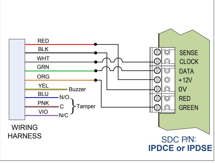
Fig. 5 Installation Wiring to IPDCE Single-Door Controller
FACTORY DEFAULTS
| Master Programming Code123456 | |
|---|---|
| Keypad Output Mode26-bit Wiegand | |
| Keypad Output Site Code000 | |
| Beeper Sounds When Key PressedYes | |
| Beeper VolumeNormal | |
| Keypad Backlight Mode30 sec after activation | |
| Keypad Timeout5 sec |
920PW OPERATION
The 920PW EntryCheck™ integrates an HID proximity reader with a 12-key digital keypad. Presenting a card/fob to proximity reader will transmit the credential's facility (site) code and card number in a standard 26-bit Wiegand output.
The Keypad may operate in one of two modes:
- (1) Wiegand Mode (default) In this mode, the keypad will emulate a reader credential. Entering a 'card' number followed by '#" will transmit the programmed facility code plus the card number as a 26-bit Wiegand output. The card number entered must be > 0 and < 65,535.
- (2) PIN Mode When this mode is enabled, each key press generates a 4-bit sequence. Enable PIN mode if the host controller supports (Card + PIN) mode, and dual authentication is desired.
ERROR ANNUNCIATION (Wiegand Mode only)
| Keypad Action | Indication |
|---|---|
| Key press timeout (in standby) | Double Beep |
| 0, or number >= 65535 is entered | Red LED flash w/ beep (x3) |
| * is entered | Red LED flash w/ beep (x3) |
| Master Code error | Red LED flash w/ beep (x3) |
BASIC PROGRAMMING
While the 920PW is in Programming Mode the yellow indicator will blink slowly.
After a programming function is selected, the yellow indicator will flash rapidly while the keypad is waiting for user input data. You will have 5 sec. between programming commands once a function is selected. The green indicator will light if the data is accepted. The red indicator will light if any programming data is entered incorrectly, and the function will have to be fully reentered.
Entering Programming Mode
The 6-digit Master Programming Code (default = 123456) is used to enter Programming Mode.
Press: # 9 # Master Code #
Master Code = the current 6-digit Master Programming Code
Exiting Programming Mode
Press: #
The red indicator will light after exiting Programming Mode
Note: The 920PW will automatically exit Programming Mode after 2 minutes of inactivity
Changing the Beeper Sound Level
The Keypad's beeper can be set to normal or low level. Remove jumper JP1 to reduce beeper sound level.
PROGRAMMING COMMANDS
Enter Programming Mode before performing any of the following commands.
Changing the 6-Digit Master Programming Code
It is recommended that the Master Programming Code be changed after the installation is finalized.
Press: 98 # Master Code # Master Code #
Master Code = The new 6-digit Master Programming Code
Beep Sounds on Keystrokes Default: Yes
Selects whether or not the keypad beeps as each key is pressed.
Press: 40 # Sound # Sound=1 for Yes, =0 for No
Selects mode for Keypad LED Backlight Default: 30 Secs.
Selects whether or not the keypad back light stays OFF, lights for 30 seconds when activated or stays ON.
Press: 52 # Output #
Output = 0, Light always OFF
= 1, 30 sec light when activated (default)
= 2, Light always ON
Change Facility (Site) Code Default: 000
Selects the Site Code when using the Keypad in Weigand Mode.
Press: 82 # Site Code #
Site Code = New 3-Digit Site Code (000-255)
Change Keypad Operation Mode Default: Wiegand Mode
Selects the Keypad Operation Mode.
Press: 83 # Mode #
Mode = 0, Wiegand Mode = 1, PIN Mode
NOTE: Once the keypad is placed into PIN Mode, it can only be returned to the default Wiegand Mode by following the Master Reset
procedure below.
RESETTING THE KEYPAD READER
Master Reset
Resets all programming options. NOTE : The Master Code will NOT be reset.
- STEP 1 Disconnect power from the keypad.
- STEP 2 Press and hold down the * and # keys.
- STEP 3 Apply power to the keypad, continue holding the keys down until the red indicator starts flashing
- STEP 4 Release the keys. The red and yellow indicators will remain lit until the process is complete, then the yellow indicator will go out.
Resetting the Master Code
- STEP 1 Remove the 920PW from the wall and disconnect power from the keypad.
- STEP 2 Locate & remove jumper JP2. Reference page 2.
- STEP 3 Re-apply power. You will get a single beep and the yellow LED will flash momentarily.
- STEP 4 Replace jumper on JP2. The Master Code is now 123456.
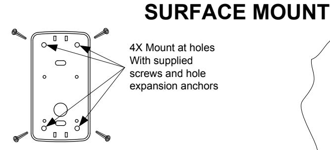
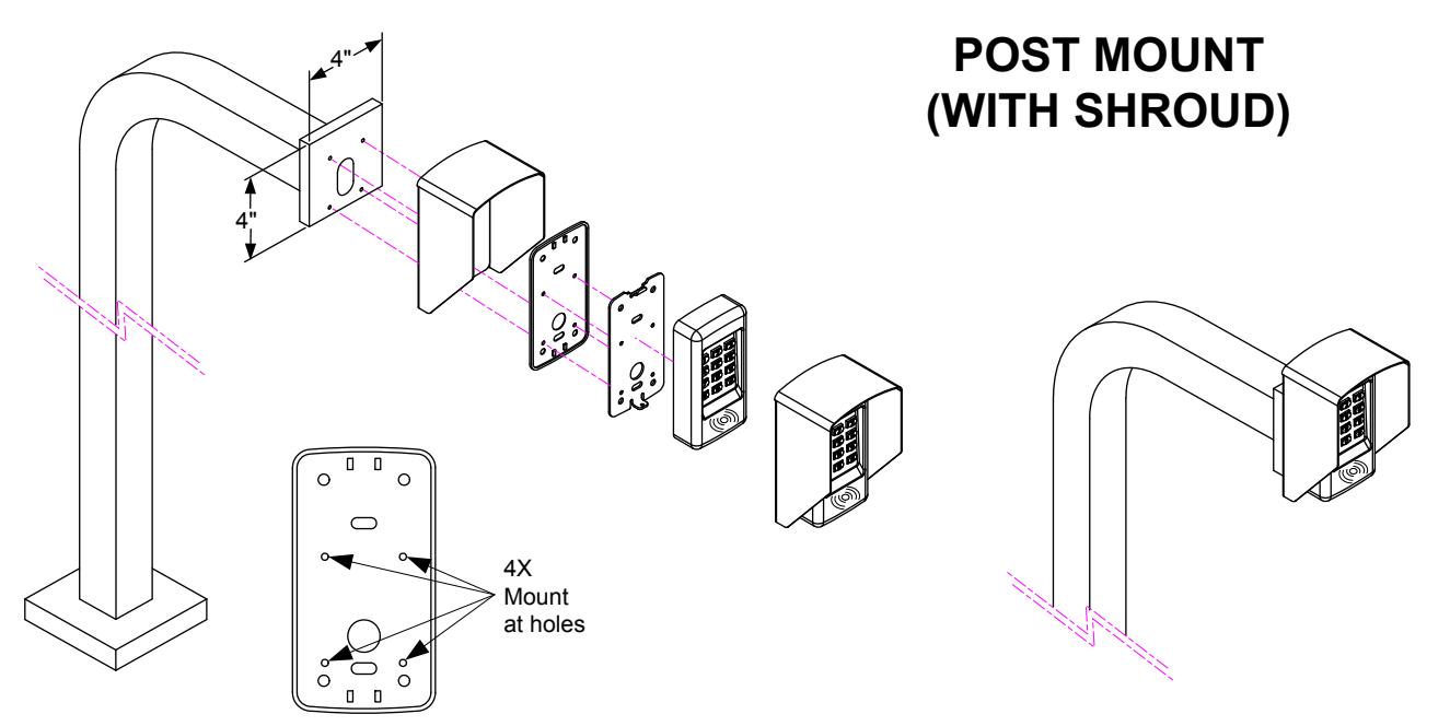
SURFACE MOUNT (WITH OPTIONAL SHROUD)
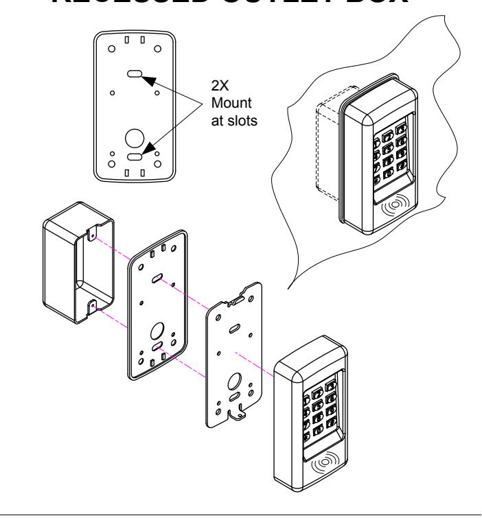
MOUNTING TO SINGLE GANG RECESSED OUTLET BOX