790-905 Installation Instructions – 75009420
Open the original PDF document
View PDF

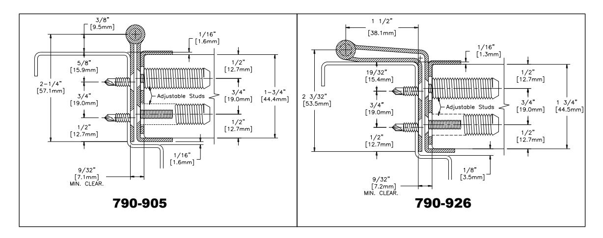
HAGER Models 790-905 and 790-926 are Stainless Steel Continuous Edge Mount Hinges for 1-3/4" (44.5mm) thick doors. They allow for minor lateral adjustment to the door after installation. Both models feature protective corner guards. Model 790-926 provides 'swing clear' rotation. Clearance required between the hinge edge of the door and the frame rabbet is 9/32" (7.1mm) minimum. For metal doors, a 1/8" (3.2mm) thick reinforcement plate is strongly recommended along the hinge edge for proper thread engagement of the adjustment studs. These models are not recommended for use on doors that have a beveled edge on the hinge side, nor for use on doors that have electrical modifications such as through-wires (ETW) or power transfer devices (EPT).
Hinge Length
All HAGER Stainless Steel Continuous Hinges are supplied 7/8" to 1" shorter than the nominal door height to avoid threshold or carpet clearance problems. If the hinge must be trimmed shorter, first determine the correct hand of the door and orientation of the hinge. Remove the bottom pin cap and trim from the bottom end of the hinge only to achieve the desired length – do not cut the top end. Undercut the pin 7/8" shorter for clearance and reinsert the bottom pin cap.
|
Nom. Door
Height |
Nom. Hinge Length |
Number of Fasteners
(Door/Frame) |
|---|---|---|
| 6'-8" | 79" (2006mm) | 19 / 19 |
| 7'-0" | 83-1/8" (2111mm) | 21 / 21 |
| 7'-2" | 85" (2159mm) | 21 / 21 |
| 8'-0" | 95" (2413mm) | 23 / 23 |
| 10'-0" | 119" (3022mm) | 27 / 27 |
Total Clearance Between Door and Frame Width
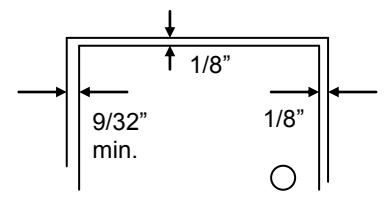
SINGLE DOOR - SQUARE EDGED
Hinge thickness 9/32" (7.1mm) Allowance for frame irregularities 1/32" (0.8mm) Latch side clearance (typical) 1/8" (3.2mm) TOTAL 7/16" (11.1mm)
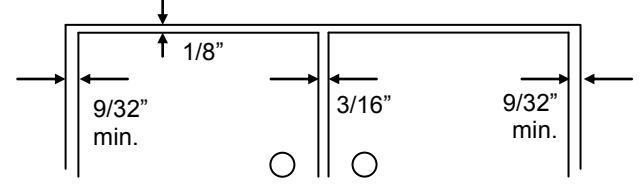
PAIR OF DOORS - SQUARE EDGED
| Hinge thickness | 9/32" | (7.1mm) | |
| Allowance for frame irregularities | (0.8mm) | ||
| Clearance between doors (typical) | (4.8mm) | ||
| Second hinge thickness | 9/32" | (7.1mm) | |
| Second allowance for frame irregularities | 1/32" | (0.8mm) | |
| Total | 13/16" | (20.6mm) | |
General Fitting Procedure
- <u>For new construction with metal doors/frames:</u> To accommodate the 9/32" (7.1mm) hinge clearance required for HAGER Models 790-905 and 790-926 order the door undersized or the frame header oversized. See the clearance information above to attain the proper finished width required. A 1/8" (3.2mm) thick reinforcement plate is strongly recommended along the hinge edge for proper thread engagement of the adjustment studs. The hinge edge of the door should not be beveled. Mortar guards, either styrofoam or wood, are recommended for frames to prevent grout from interfering with the installation of the hinge fasteners.
- <u>For new site-hung wood doors:</u> If necessary, scribe and cut from the latch edge of the door to leave sufficient hinge stile thickness for proper fastening. A minimum clearance of 9/32" (7.1mm) is required between the hinge edge of the door and the frame rabbet. Do not bevel the hinge edge of the door. See the clearance information above to attain the proper finished width of the door.
- <u>For remodeling with existing wood or laminate doors:</u> If necessary, scribe and cut from the hinge edge of the door and plane smooth. A minimum clearance of 9/32" (7.1mm) is required between the hinge edge of the door and the frame rabbet. Do not bevel the hinge edge of the door. See the clearance information above to attain the proper finished width of the door.

Installation Procedure
Frame Preparation
- 1. With the hinge open, place the hinge frame leaf against the frame rabbet. Position the top of the hinge 1/8" (3.2mm) below the header. Allow 1/16" (1.6mm) between the frame stop and the edge of the hinge.
- 2. Mark and center punch the screw hole locations. Accurate location is important for proper hinge installation.
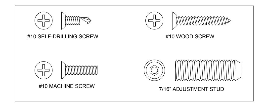
- 3. For metal frames 14 gage or less (≤.080"/2.0mm) it is not necessary to pre-drill pilot holes if using the self-drilling screws provided. For metal frames 12 gage and over (≥.093"/2.3mm) drill and tap all mounting holes for #10-24 threads prior to installing the screws. For wood frames, pre-drill pilot holes using a #25 (.149"/3.8mm) bit.
- 4. Do not attach the hinge to the frame at this time.
Door Preparation
- 1. With the hinge open, place the hinge door leaf against the edge of the door. Position the integral corner guard fully against the 'push' face of the door. Position the top of the hinge flush with the top of the door.
- 2. Mark and center punch the screw hole locations. Accurate location is important for proper hinge installation .
- 3. For wood doors, drill pilot holes using a Z (.413"; 10.5mm) bit to a minimum depth of 1-3/8" (35mm). For reinforced metal doors, drill pilot holes using a 25/64" (9.9mm) bit and tap for 7/16"-20 threads.
- 4. Using a 3/16" Allen wrench, screw a 7/16" Adjustment Stud into each hole. Insert each stud until it is flush with the edge of the door. The studs are designed for a tight friction fit in the holes so they will not turn when the mounting screws are being tightened. If the Adjustment Studs turn too freely, apply LOCTITE (for threaded joints) to the stud's external threads during installation.
Hanging the Door
- 1. Place the separate Protective Corner Guard component into position on the door edge and fully against the 'pull' face of the door. Place the hinge door leaf over it making certain the integral corner guard is fully against the 'push' face of the door. Install a #10 machine screw in the top two and bottom two hole locations only and fully tighten. Do not install the remaining screws in the door leaf at this time.
- 2. Position the door (with hinge attached) at 90 to the frame. Attach the hinge to the frame rabbet. For metal frames, use the #10 self-drilling screws provided (recommended driver speed 1,900-2,500 RPM). For wood frames, use the #10 wood screws.
- 3. Make a gentle trial swing. Carefully check for proper swing and door clearances.
Adjusting the Door
- 1. If lateral adjustment of the door is required due to excessive or uneven door/frame clearance, make adjustments using either the top two and/or bottom two screws installed in the door. It is not necessary to remove the hinge from the door to make adjustments.
- 2. Remove one of the two screws and insert a 3/16" Allen wrench through the hole into the Adjustment Stud. It may be necessary to slightly loosen the second screw while rotating the Adjustment Stud outward to the desired position. Then adjust the second Stud in the same manner. Re-insert and tighten the #10 machine screws when complete.
- 3. Make any necessary adjustments at the other end of the hinge in the above manner until the proper door fit is achieved.
- 4. Using a 3/16" Allen wrench, adjust all remaining studs until each rests against the back of the hinge leaf.
- 5. Install #10 machine screws into all remaining holes and tighten.
- 6. Make a gentle trial swing. Carefully check for proper swing and door clearances.