790-904_906 Installation Instructions – 75009404_1-21-08
Open the original PDF document
View PDF

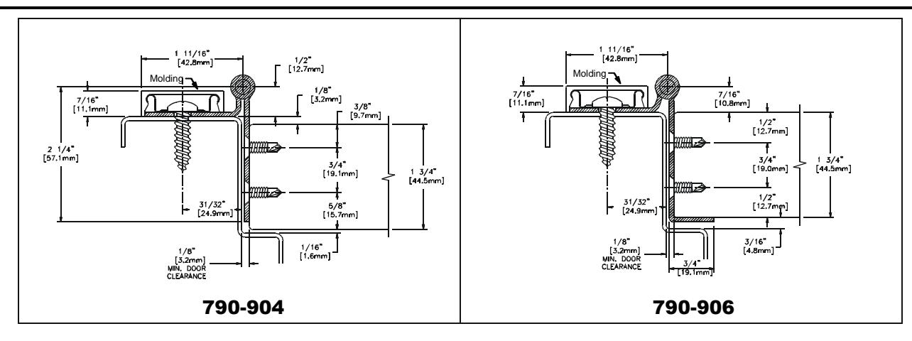
HAGER Models 790-904 and 790-906 are Stainless Steel Continuous Half Edge Mount Hinges for 1-3/4" (44.5mm) thick doors. The frame face must have a flat surface at least 1-5/8" wide. Clearance required between the hinge edge of the door and the frame rabbet is 1/8" (3.2mm) minimum. Model 790-906 features an integral protective corner guard and is not recommended for use on doors that have a beveled edge on the hinge side .
Hinge Length
All HAGER Stainless Steel Continuous Hinges are supplied 7/8" to 1" shorter than the nominal door height to avoid threshold or carpet clearance problems. If the hinge must be trimmed shorter, first determine the correct hand of the door and orientation of the hinge. Remove the bottom pin cap and trim from the bottom end of the hinge only to achieve the desired length – do not cut the top end. Undercut the pin 7/8" shorter for clearance and reinsert the bottom pin cap.
|
Nom. Door
Height |
Nom. Hinge Length | NUMBER OF FASTENERS (Door/Frame) | |
|---|---|---|---|
| 6'-8" | 79" (2006mm) | 19 / 13 | |
| 7'-0" | 83-1/8" (2111mm) | 21 / 14 | |
| 7'-2" | 85" (2159mm) | 21 / 14 | |
| 8'-0" | 95" (2413mm) | 23 / 15 | |
| 10'-0" | 119" (3022mm) | 27 / 18 | |
Total Clearance Between Door and Frame Width
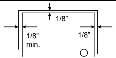
SINGLE DOOR - SQUARE EDGED
Hinge side clearance (minimum) 1/8" (3.2mm) Allowance for frame irregularities Latch side clearance (typical) 1/8" (3.2mm) TOTAL* (0.8mm) 1/8" (3.2mm) 1/8" (3.2mm) 1/8" (3.2mm) 1/8" (7.1mm)
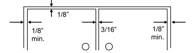
Pair of Doors - Square Edged
| Hinge side clearance (minimum) | (3.2mm) | |
| Allowance for frame irregularities | (0.8mm) | |
| Clearance between doors (typical) | (4.8mm) | |
| Second hinge side clearance (minimum) | (3.2mm) | |
| Second allowance for frame irregularities | 1/32" | (0.8mm) |
| TOTAL | * 1/2" | (12.7mm) |
* For doors that are pre-beveled 1/8"-in-2" on the hinge edge, add 1/32" (0.8mm) <u>per door</u> to the TOTAL clearance shown (Model 790-904 only). For Model 790-906, the hinge edge of the door should not be beveled.
General Fitting Procedure
For new construction with metal doors/frames: To accommodate the 1/8" (3.2mm) minimum hinge clearance required for HAGER Model 790-904 and 790-906, order the door undersized or the frame header oversized. See the clearance information above to

Installation Instructions HAGER Models: 790-904 and 790-906 Rev. 1/21/08
- attain the proper size. Mortar guards, either styrofoam or wood, are recommended for frames to prevent grout from interfering with the installation of the hinge fasteners.
- For new site-hung wood doors: If necessary, scribe and cut from the latch edge of the door to leave sufficient hinge stile thickness for proper fastening. See the clearance information above to attain the proper finished width of the door. A minimum clearance of 1/8" (3.2mm) is required between the hinge edge of the door and the frame rabbet.
- For remodeling with existing wood or laminate doors: If necessary, scribe and cut from the hinge edge of the door and plane smooth. See the clearance information above to attain the proper finished width of the door. A minimum clearance of 1/8" (3.2mm) is required between the hinge edge of the door and the frame rabbet.
Installation Procedure
Door Preparation
- 1. With the hinge open, place the hinge door leaf against the edge of the door. Position the top of the hinge flush with the top of the door. For the 790-904, to achieve a 1/8" inset, position the 'pull' face of the door 5/8" from the center of the hinge pin. For the 790- 906, position the integral corner guard fully against the 'push' face of the door.
- 2. Mark and center punch the screw hole locations. Accurate location is important for proper hinge installation.
- 3. For metal doors 14 gage or less (≤.080"/2.0mm) it is not necessary to pre-drill pilot holes if using the #10 self-drilling screws provided. For metal doors 12 gage and over (≥.093"/2.3mm) drill and tap all mounting holes for #10-24 threads prior to installing the screws. For wood doors, pre-drill pilot holes using a #25 (.149"/3.8mm) bit.
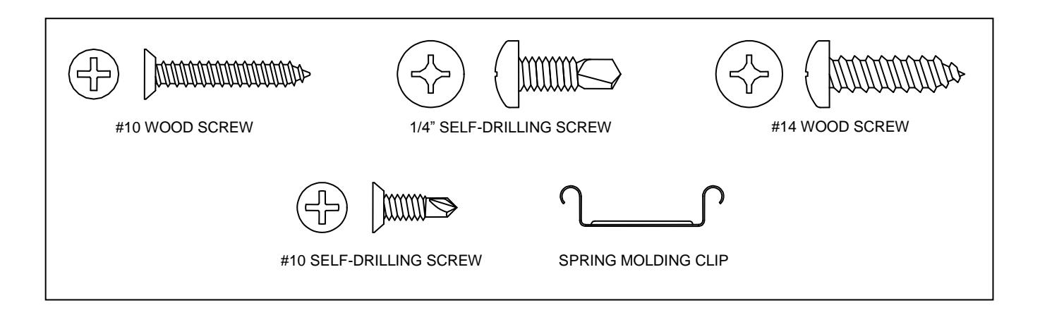
- 4. Attach the hinge to the door. For metal doors, use the #10 self-drilling screws provided (recommended driver speed 1,900-2,500 RPM). For wood doors, use the #10 wood screws provided.
Hanging the Door
- 1. With the hinge mounted to the door, set the door into the frame using shims or wedges to adjust for the desired clearance on all sides. Allow 1/8" (3.2mm) clearance between the top of the door and the frame header rabbet. Allow 1/16" (1.6mm) minimum clearance between the hinge door leaf and the frame rabbet.
-
2. With the door held securely in place, rotate the hinge leaf into position on the face of the frame.
- a) For metal frames, mark and center punch the hole locations on the frame face. For metal frames 12 gage or less (≤.093"/2.0mm) it is not necessary to pre-drill pilot holes if using the 1/4" self-drilling screws provided. For thicker metal frames, pre-drill pilot holes using a 7/32" (5.5mm) bit. Install the 1/4" self-drilling screws (recommended driver speed 1,900-2,500RPM), placing a Molding Clip under the head of a screw at five locations along the hinge - one at each end and the others spaced equally in between.
- b) For wood frames, mark and center punch the hole locations on the frame face. Pre-drill pilot holes using a 7/32" (5.5mm) bit. Install the #14 wood screws, placing a Molding Clip under the head of a screw at five locations along the hinge - one at each end and the others spaced equally in between.
- 3. Remove all shims and wedges and make a gentle trial swing. Carefully check the door for proper swing and clearance.
Install the Snap-On Molding
1. Position the Molding so that the short leg is closest to the hinge pin. Hook the short leg over the Molding Clips along the full length of the hinge. Starting at the top and working downward press the long leg of the Molding in place completely over the outside edge of the door leaf. If necessary, gently tap in place using a rubber mallet, taking care not to damage the Molding.