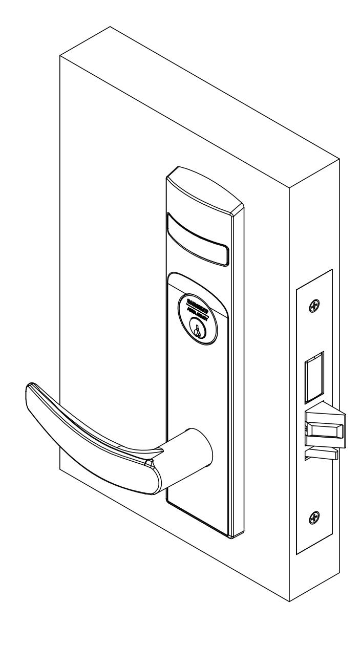
7800 and 8200 Series Mortise Lock Used with VN1 Escutcheon Trim and V Series Indicators
Open the original PDF document
View PDFInstallation Instructions

7800 & 8200 Series Mortise Lock
Used with VN1 Escutcheon Trim and V Series Indicators
WARNING
Attention Installer: Improper installation may result in damage to the product and void the factory warranty.
Used with VN1 Escutcheon Trim and V Series Indicators
Installation Instructions

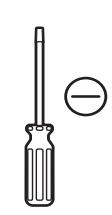
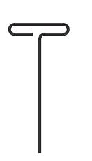
1 Tools Required
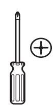
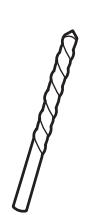
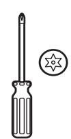
#2 & #3 Phillips head screwdrivers
Flat blade screwdriver
1/8" Allen Wrench
3/8" Drill bit T-20 Torx Screw with Tamper Pin Driver
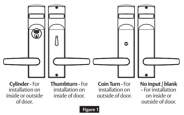
2 Indicator Variants
Depending on function and option ordered, indicators are provided in the following variations, these instructions detail how to install with cylinder, however other variations follow similar instructions. (Figure 1)
Contact factory for any questions.
1-800-727-5477 • www.sargentlock.com
3 Lock set configuration
To set function of multi-function lock or to re-hand, see instructions on lock body.
Used with VN1 Escutcheon Trim and V Series Indicators
Installation Instructions

4 Rehanding indicator (if required)
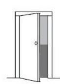
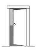
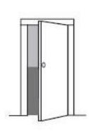
Indicator spindle cams MUST be oriented correctly per lock function and door mounting location. Verify hand and bevel of door. (Figure 2)

Scan this QR code for the Sargent Indicator Handing Charts
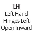
LHRB Left Hand Reverse Bevel Hinges Left Open Outward
RH Right Hand Hinges Right Open Inward
RHRB Right Hand Reverse Bevel Hinges Right Open Outward
Figure 2
Stand outside of locked door when determining door hand.
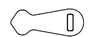
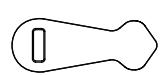
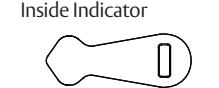
Next, verify inside and/or outside indicators are handed correctly, using Spindle Cam Position chart. (Figure 3)
If they are handed correctly, skip to Step 5 "Prepare Door".
If they are not handed correctly:
- 1. Remove indicator back plate by pulling out from top slot, then remove spindle cam from assembly. (Figure 4)
- 2. Position spindle cam in correct direction for door hand. (Figure 3)
Important:
- For thumbturn indicators, make sure thumbturn is positioned in 12 o'clock direction as shown. (Figure 5)
- 3. Slide spindle cam post into the correct slot of the display slide. (Figure 4)
- 4. Re-seat back plate into original position.
- 5. Return indicator to vacant/unlocked position for installation.
Spindle Cam Position for Locks with Deadbolt (*and 56 function)

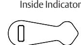

Door Hand: LH / LHRB
Inside Indicator
Outside Indicator
Door Hand: RH / RHRB Spindle Cam Position for Locks without Deadbolt (*except 56 function)
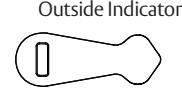
Door Hand: LH / LHRB
Outside Indicator
Inside Indicator
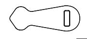
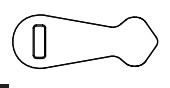
Figure 3
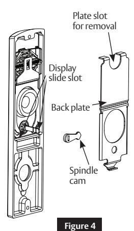
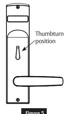
Figure 5
A8260E 3/23
Used with VN1 Escutcheon Trim and V Series Indicators
Installation Instructions
5 Installation
a Prepare Door
Prepare door for function holes, size, and location according to A8258 door marker template, if not already prepped.

b Install Lock
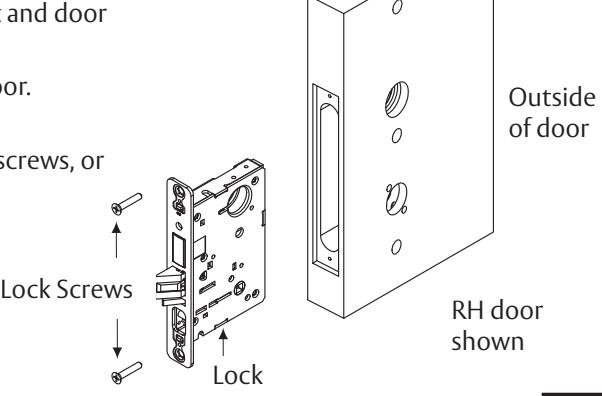
- 1. Verify strike location according to template. Clean out door pocket and door edge of debris.
- 2. Ensure handing of lock matches handing of door. Slide lock into door. (Figure 6)
- 3. Temporarily hand tighten two (2) lock screws (#12 x 1-1/4" wood screws, or #12-24 x1/2" machine screws).
Notes:
• Keep door open until installation is complete.
Inside of door
Figure 6

c Install Outside Trim
- 1. Verify lock is in unlocked state (control hub slot should be vertical). Also, verify indicator is in vacant/unlocked position.
- 2. Align trim posts with diagonal holes in door, be sure lever is horizontal. Slide outside escutcheon assembly through lock body from outside door face. (Figure 7)
Note:
1-800-727-5477 • www.sargentlock.com
If indicator is used on outside, align indicator spindle with control hub.
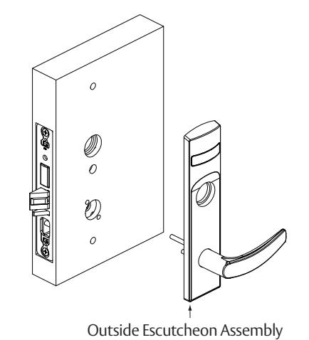
Figure 7
Used with VN1 Escutcheon Trim and V Series Indicators
Installation Instructions
5 Installation, continued
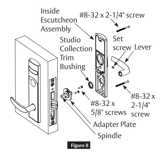
d Install Inside Trim
- 1. Slide spindle into lockbody hub. (Figure 8)
- 2. Slide adapter and plate assembly over spindle.
- 3. Secure with two (2) #8-32 x 5/8" screws.
- 4. For Studio Collection levers only, use trim bushing over adapter plate.
- 5. Verify lock is in unlocked state (turn outside lever to ensure). Also, Verify indicator is in vacant/unlocked position.
- 6. Align escutcheon over adapter and install inside escutcheon assembly onto inside door face.
Note:
- If indicator is used on inside, align indicator spindle with control hub.
- 7. Through-bolt inside escutcheon to outside escutcheon with two (2) #8-32 x 2-1/4" screws.
- 8. Install inside lever on adapter plate. Secure with set screw.
Note:
Screw heads should be visible on inside escutcheon.

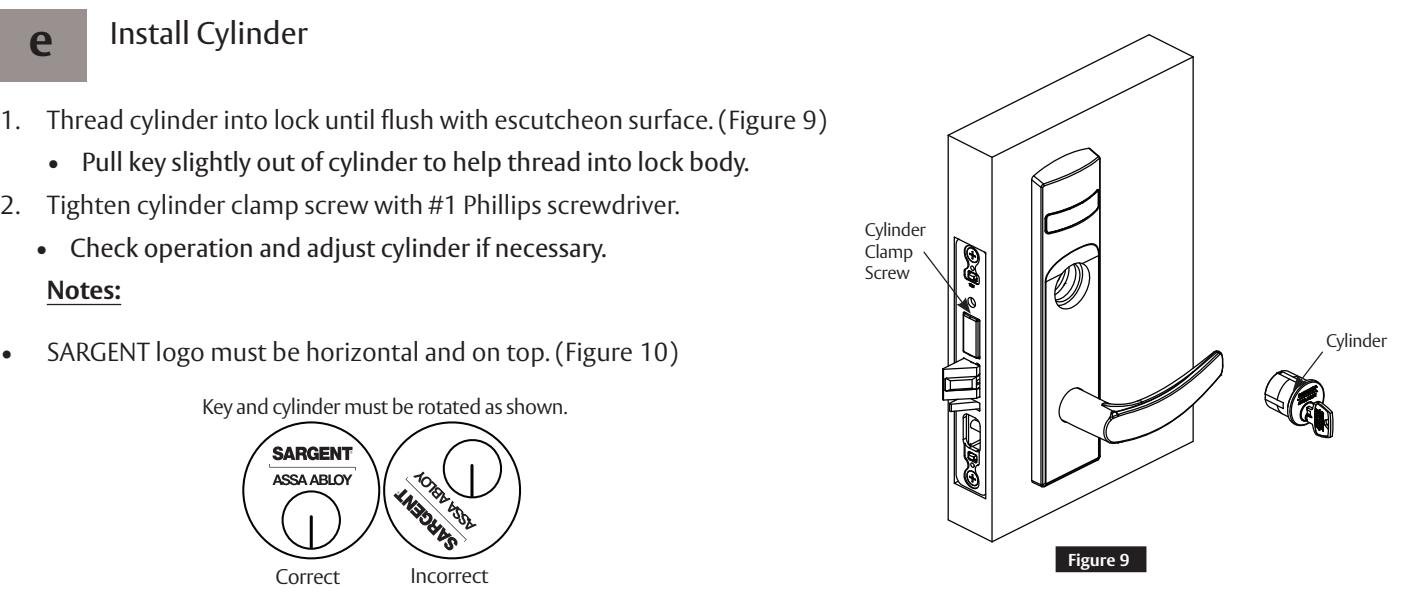
e Install Cylinder
-
1. Thread cylinder into lock until flush with escutcheon surface. (Figure 9)
- Pull key slightly out of cylinder to help thread into lock body.
-
2. Tighten cylinder clamp screw with #1 Phillips screwdriver.
- Check operation and adjust cylinder if necessary.
Notes:

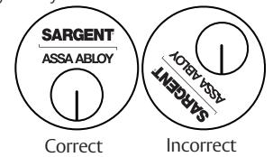
Figure 10
- If double cylinder function is used, repeat steps 1 and 2 for second cylinder.
- Removable Core or Interchangeable Core cylinders require a control key (key stamped with C) to remove and install the core. This is not provided standard. It must be requested separately. If requesting 1-bitted control key, specify 113511 cut.

1-800-727-5477 • www.sargentlock.com
A8260E 3/23
Used with VN1 Escutcheon Trim and V Series Indicators
Installation Instructions

f Install Outside Front
- 1. Tighten the two (2) lock screws completely. (Figure 11)
- 2. Attach outside front with two (2) flat head screws #8-32 x 1/4".
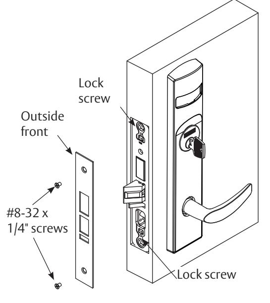
Figure 11
g Perform Functional Check
DO NOT FORCE if resistance is encountered during functional check. Refer back to Rehanding Indicator (if required) section to ensure correct handing. Rehand if necessary.
-
1. Insert key into cylinder (if present) and rotate:
- Ensure there is no friction against lock case or any other obstructions.
-
2. Check key retracts latch:
- Key should rotate freely.
-
3. Throw deadbolt (if present):
- Check key retracts both deadbolt and latch.
-
4. Test levers:
- Confirm latch and deadbolt (if installed) retract.
- 5. Verify indicator displays correct status when locked and unlocked.
Used with VN1 Escutcheon Trim and V Series Indicators
Installation Instructions
6 Indicator Parts List
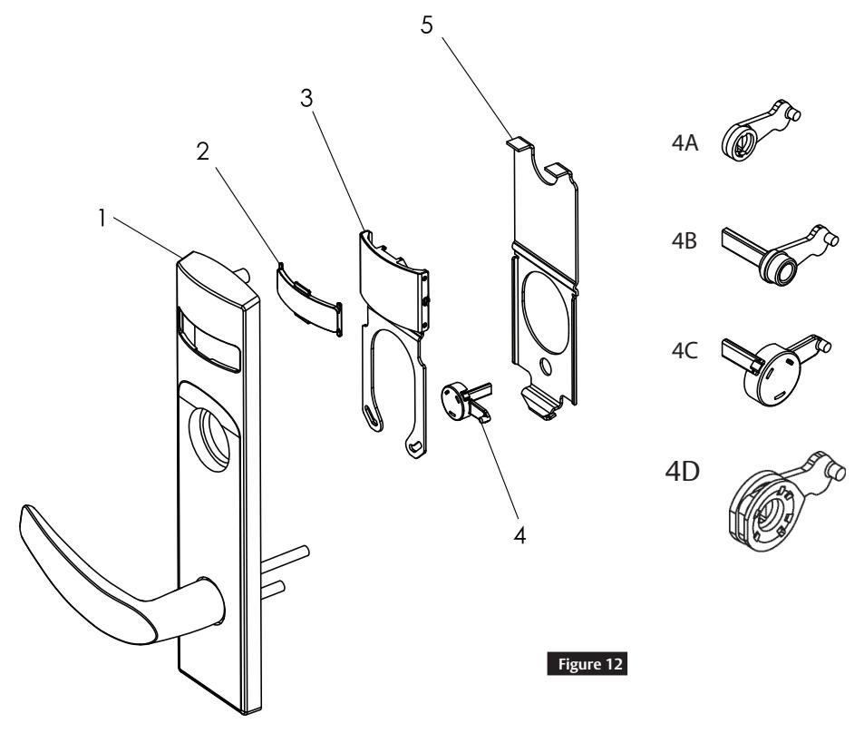
| Figure 12 | Description | Part Number | Req. |
|---|---|---|---|
| 1 | VN1 Indicator Escutcheon | Consult Factory | 1 |
| 2 | Indicator Window | 81-0811 | 1 |
| 3 | Indicator Display Assembly - Green Unlocked / Red Locked | 82-5602 | 1 |
| Indicator Display Assembly - Green Vacant / Red Occupied | 82-5603 | ||
| Indicator Display Assembly - Green Unlocked Icon / Red Locked Icon | 82-5604 | ||
| Indicator Display Assembly - White Unlocked / Red Locked | 82-5605 | ||
| Indicator Display Assembly - White Vacant / Red Occupied | 82-5606 | ||
| Indicator Display Assembly - White Unlocked Icon / Red Locked Icon | 82-5607 | ||
| Indicator Display Assembly - Green Ouvert / Red Fermé | 82-5684 | ||
| Indicator Display Assembly - Green Libre / Red Occupée | 82-5685 | ||
| 4A | Indicator Spindle Cam - Thumbturn / Coin Turn | 81-0745 | 1 |
| 4B | Indicator Spindle Cam - Cylinder / No Input / Blank | 81-0756* | 1 |
| 4C | Indicator Spindle Cam - 05, 37, 38, 59 Functions | 82-5577* | 1 |
| 4D | Indicator Spindle Cam - 05 (Inside) | 82-5673 | 1 |
| 5 | Indicator Backing Plate | 81-0748 | 1 |
| 6 | VN1 Escutcheon Screw Pack (Not shown) | 82-5587 x finish* | 1 |
| 7 | Door Marker Template (Not shown) | A8258 | 1 |
* These parts are for 1-3/4" standard thickness doors. For other thicknesses, please contact factory.
Note:
Reference 8200 Series parts manual for all lock body parts.


This product can expose you to lead which is known to the state of California to cause cancer and birth defects or other reproductive harm. For more information go to www.P65warnings.ca.gov.