7800 Mortise Lock with PT Paddle Trim Installation Instructions
Open the original PDF document
View PDFInstallation Instructions

7800 Series
with PT Paddle Trim
Mortise Lock

This product can expose you to lead which is known to the state of California to cause cancer and birth defects or other reproductive harm. For more information go to www.P65warnings.ca.gov.
7800 Series
Mortise Lock with PT Paddle Trim
Installation Instructions

| TOC | Table of Contents |
|---|---|
| 1 |
Tools Required
2 |
| 2 |
Installation of Lock
2 |
| 3 | Installation of Cylinder3 |
| 4 | Determine Orientation and Handing of Trim3 |
| 5 | Installation of Chassis4 |
| 6 |
Installation of Paddles and Covers
4 |
| 7 | 7800 PT Multi Function Lock Instructions5 |
| a | How to Change Function of Lock5 |
| b | Item Chart5 |
| c | How to Change Hand of Lock6 |
| 1 | Tools Required |
- Phillips Screwdriver #2
- Drill
- 7/46" Drill Bit (Wood Door)
- #8-32 Tap (Metal Door)
- 0.136 (#18) Tap Drill
- Screw Pack with screws for lockbody, fronts & strike screws (part #77-4236)
- T15 Torx Bit
- 1/8" Allen Key
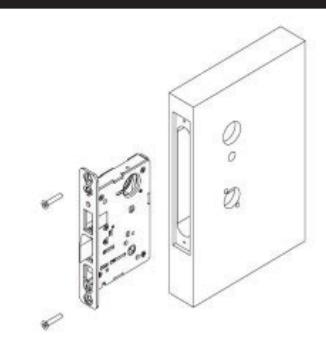
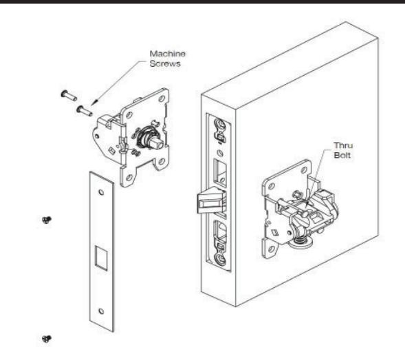
2 Installation of Lock
- Slide Lock into the door.
- Secure lock in door with (2) wood screws #12 x 1-1/4" or machine screw #12-24 x 1/2".
- Do not tighen screws fully at this point.
1-800-727-5477 • www.sargentlock.com
A8130D 02/20
Installation Instructions

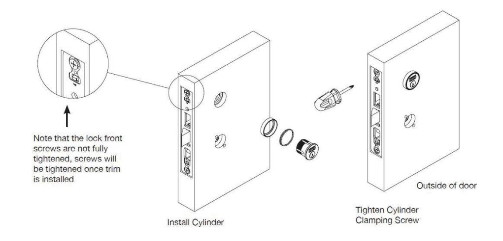
3 Installation of Cylinder
For non-cylinder functions, proceed to STEP 4
- Thread the cylinder into the lockbody.
- Verify the cylinder is flush with the collar and the logo is horizontal.
- Secure cylinder with cylinder clamping screw located above the deadbolt opening.
- Verify the cylinder functions correctly.
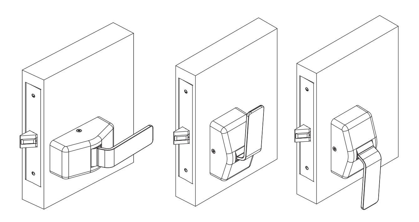
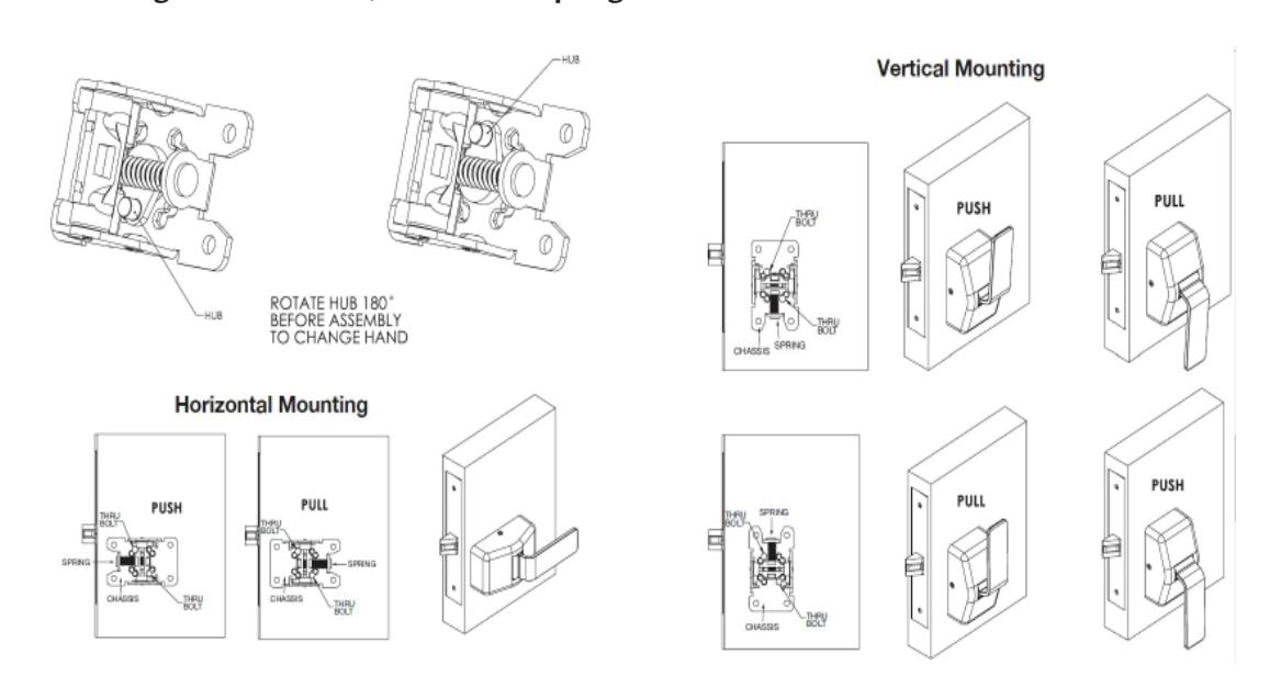
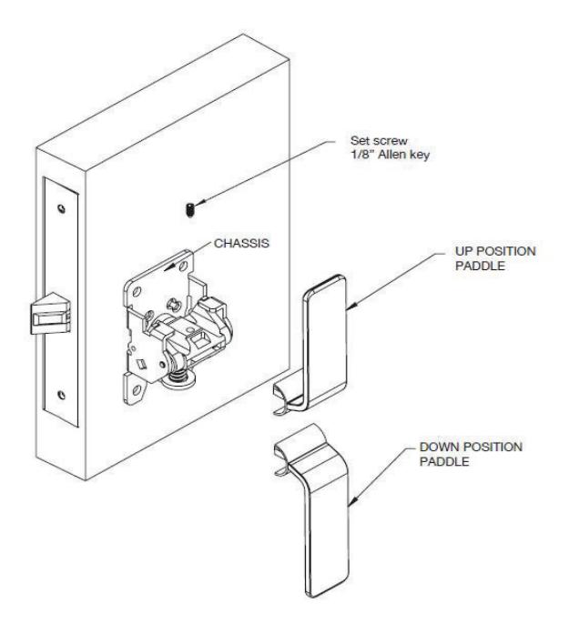
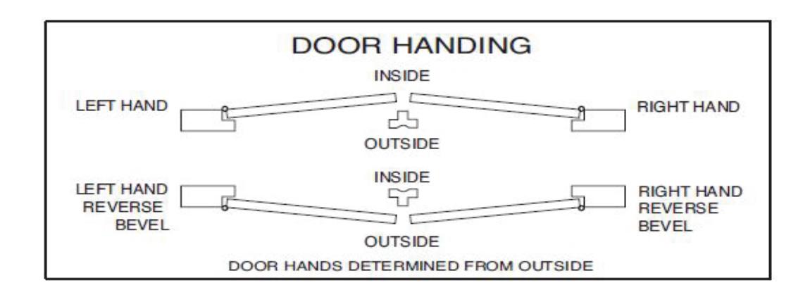
4 Determine Orientation and Handing of Trim
The trim can be mounted vertically or horizontally.
- Down or horizontal paddle orientation is required for cylinder side of door.
- Horizontal paddle orientation is required if thumb turn or an emergency release is used.
- To change from PUSH to PULL orientation, chassis will need to be turned 180º and paddle installed in the correct direction.
NOTE: Chassis is packed with the paddle attached. Remove paddle before installing. Before installing chassis to door, confirm the spring orientation is correct.
1-800-727-5477 • www.sargentlock.com
A8130D 02/20
Installation Instructions

5 Installation of Chassis
- Check handing of chassis before installing mounting screws.
- Insert the (2) mounting posts through the outside chassis, then secure with (2) #8-32 x 5/8" machine screws through the inside chassis. Do not tighten fully at this point.
- Lockbody screws on edge of door are to be securely fastened at this point.
- Level chassis.
- Tighten thru bolt screws.
- Attach the outside front plate to lock front with (2) #8-32 x 1/4" flat head screws.
- Tighten all screws firmly. Do not over tighten.
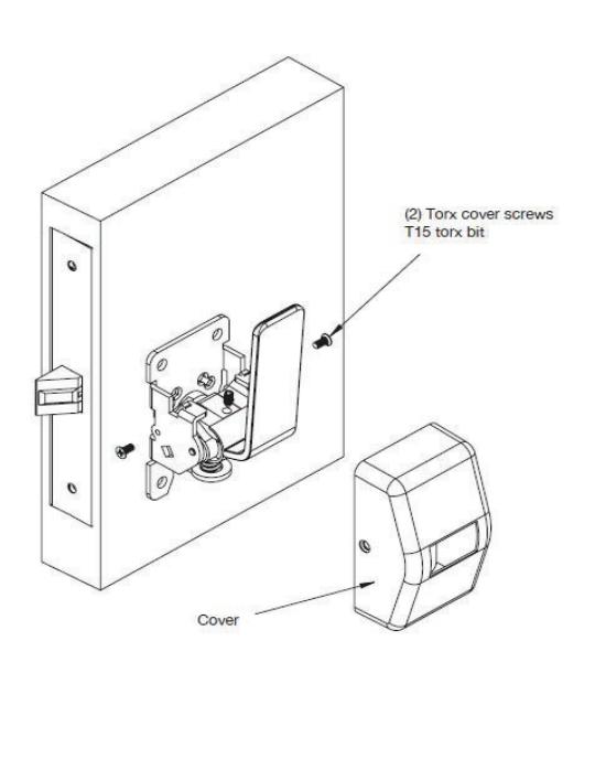
6 Installation of Paddles and Covers
- •Insert paddle in slot.
- Install set screw.
- •Slide cover over paddle and align with mounting holes.
- Install cover screws.
Installation Instructions

7
7800 PT Multi Function Lock Instructions
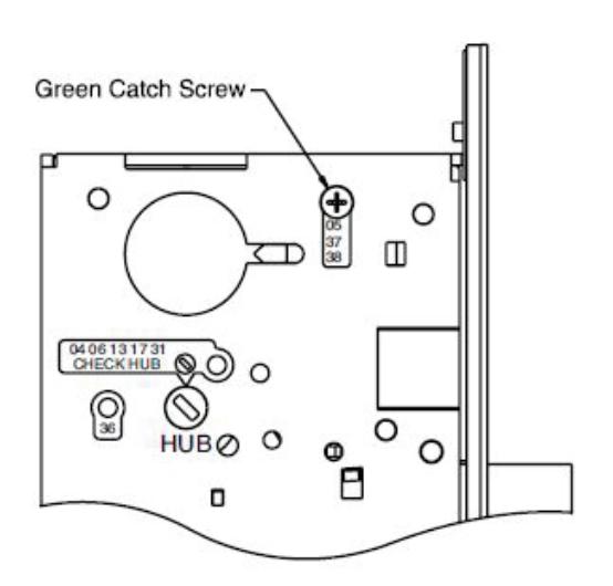
a How to Change Function of Lock
The green catch screw must be located as designated on lock case to create desired function.
3 locations:
- •One for 05, 37 & 38 functions
- (15 function in unlocked position)
- •One for 04, 06, 13, 17 & 31 functions
- •One for 36 function
NOTE: When moving green catch screw to 04, 06, 13, 17 & 31 functions, hub position must be at 45° as shown on lockcase.
NOTE: 17 function requires both levers to be rigid. Rotate red locking piece 90°, so red surface of slide faces back of lockbody.
7800PT lockbody is required when using PT paddle trim, 8200 lever lockbody will not function properly with the PT trim
b
Items Needed to Create Each of the Following Functions
| Function |
Outside
Lever |
Inside Lever |
Trim One
Side Kit |
Outside
Cylinder |
Inside
Cylinder |
Thumb Turn |
| 04 | Х | Х | Х | |||
| 05 | Х | Х | Х | X*** | ||
| 06 | Х | Х | Х | |||
| 13 | Х | Х | ||||
| 17 | Х | Х | Х | Х | ||
| 31 | Х | X | Х | |||
| 36 | Х | Х | Х | |||
| 37 | Х | Х | Х | |||
| 38 | Х | Х | Х | Х |
#41 Cylinder is standard for both single & double cylinder functions for 1-3/4" thick door
NOTE: Trim-one-side functions always require an inside trim assembly which can be used on the inside or outside of the door
Installation Instructions

7 7800 PT Multi Function Lock Instruction (continued)
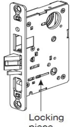
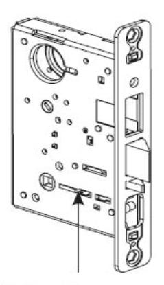
c How to Change Hand of Lock
NOTE: Red surface of locking piece must face secure (keyed/locked) side of door.
To rotate locking piece:
- 1. Position lockbody with red surface of locking piece visible.
- 2. Insert blade type screwdriver into locking piece slot to rotate locking piece.
- 3. Push locking piece toward back of lock body and rotate 180° until RED surface shows on opposite side.
NOTE: 04, 06, 13, 17 and 31 Functions require:
- (a) Green catch screw to be removed.
- (b) Rotate hub 45° to vertical position.
- (c) Rotate locking piece for required hand.
- (d) Red surface faces locked side of door.
- (e) Rotate hub to the original 45° position as shown on lockcase.
- (f) Green catch screw is then reinstalled.
NOTE: Beveled surface of latch must face strike. The deadlatch is self adjusting. To change hand of latch:

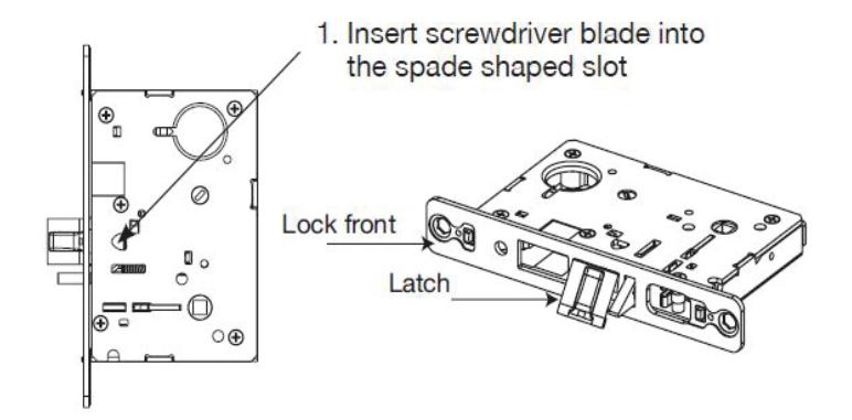
2. Rotate screwdriver 90º to push latch out until back of latch clears lock front. Then rotate latch 180º. Latch will then re-enter lockbody. (Note: Latch can not be unscrewed)
7800 Series
Mortise Lock with PT Paddle Trim
Installation Instructions

A8130D 02/20 1-800-727-5477 • www.sargentlock.com

SARGENT Manufacturing Company 100 Sargent Drive New Haven, CT 06511 USA 800-727-5477 www.sargentlock.com
Founded in the early 1800s, SARGENT ® is a market leader in locksets, cylinders, door closers, exit devices, electro-mechanical products and access control systems for new construction, renovation, and replacement applications. The company's customer base includes commercial construction, institutional, and industrial markets.