7000Series_InstallationInstructions_I-CL00834-Rev02
Open the original PDF document
View PDF

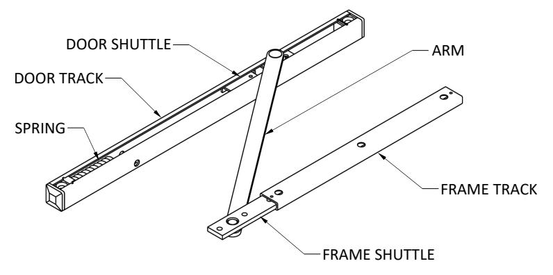
1. PARTS
| Application | QTY | Screw Type | |||||
|---|---|---|---|---|---|---|---|
| Metal Door | 2 | 1/4-20x1-3/4" FPHMS | |||||
| Metal Frame | 3 | 1/4-20 x 1/2" FPHMS | |||||
| Wood Door | 2 | #18 x 3" PPHWS | |||||
| Wood Frame | Not Available | ||||||
Pre Installation Notes:
- 1. Hollow metal frames must be properly reinforced with a 3/16" thick plate, as shown in Section 2 of these instructions.
- 2. Hollow metal doors must be properly reinforced with a 3/16" thick plate, as shown in section 2 of these instructions.
- 3. Hold open (7017) and Friction (7015) are not permitted for use on fire doors.
2. DOOR AND FRAME PREP DIMENSIONS
The door and frame must be prepared according to the following diagrams and the information in section 3 of these instructions. Make sure to add proper blocking in the top rail of the door where necessary. ال ک HINGE MORTISE WIDTH 1- 1/9" CENTERED ON DOOR HINGE or PIVOT CI Single Action Door requires the arm cut out (Dim D) from the push side of the door to the far edge of the door track mortise, as shown here. NOTE | 1 FRAME TRACK MORTISE DEPTH 1/2" FRAME REINFORCEMENT 12-9/16" " NOTE 2 MORTISE WIDTH 1-1/ CENTERED ON RABBÉT DOOR TRACK MORTISE DEPTH 1-7/16 ARM CUT OUT DEPTH 1/4" DOOR REINFORCEMENT
7017 Series Hold Open requires a fastener recess.
The optional hole enables the 7017 Series hold open function to be turned on and off with the use of a flat head screwdriver without removing the Door Track from the door after installation. This hole only needs to be drilled through one side of the door and will be visible.
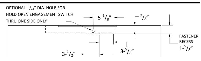
Double Action Door only requires the arm cut out (Dim D) across the entire door thickness, as shown here.

Rev 2, Rev Date: 1/8/2024 Page 1 of 2
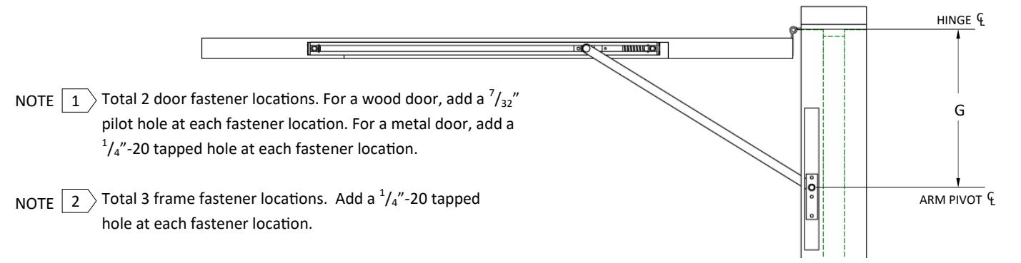
3. INSTALLATION DIMENSIONS
|
Stop
Size |
Door Frame
Opening |
А | В | С | D | E | F | G (Reference Only) Degree of Door Opening | |||||
|---|---|---|---|---|---|---|---|---|---|---|---|---|---|
| 85° | 90° | 95° | 100° | 105° | 110° | ||||||||
| Size 3 | 27" to less than 30" | 4-9/16" | 20-11/16" | 0" | 22-0" | 19-3/8" | 1-1/8" | 7- 5 / 8 " | 6-1/8" | 5-0" | 4-0" | 3-1/8" | 2-3/4" |
| Size 4 | 30" to less than 36" | 4-1/2" | 23-15/16" | 0" | 25- 1 / 8 " | 22-5/8" | 3-3/4" | 10-1/4" | 8-13/16" | 7-5/8" | 6-5/8" | 5-3/4" | 5-3/16" |
| Size 5 | 36" to less than 40" | 5- 1 / 16 " | 26- 5 / 16 " | 4-0" | 25- 1 / 4 " | 25-0" | 5-1/4" | 11-15/16" | 10-9/16" | 9-7/16" | 8-3/8" | 7- 7 / 16 " | 6-11/16" |
| Size 6 | 40" to less than 44" | 8-3/4" | 30- 1 / 16 " | 8-0" | 27- 9 / 16 " | 28-3/4" | 6-3/8" | 14-3/4" | 13-1/8" | 11-5/8" | 10-7/16" | 9-1/8 | 8-3/16" |
| Size 7 | 44" to 52" | 11-3/4" | 31-1/16" | 11-0" | 28-1/2" | 29-3/4" | 6- 7 / 8 " | 15-3/4" | 13-7/8" | 12-1/8" | 10-5/8" | 9-5/16" | 8-1/4" |
4. INSTALLATION INSTRUCTIONS
- 1. Use the fasteners indicated in Section 1 of these instructions to fasten the Door Track into the door mortise. The spring end of the Door Track must be toward the hinge side of the door. For Hold Open (7017), be sure to set the Hold Open engagement switch to the desired position (indicated in the image below) before placing the Door Track into the door mortise.
- 2. With the Frame Shuttle inside the Frame Track, use the fasteners indicated in Section 1 of these instructions to fasten the Frame Track into the frame mortise. The short end of the Frame Shuttle must be toward the hinge side of the frame.
- 3. Use the set screws to fix the location of the Frame Shuttle according to the diagram and chart in Section 3 of these instructions
- 4. Test to ensure that the door can freely open and stops at the desired angle. Adjust the Frame Shuttle location as necessary.
- 5a. For Hold Open (7017), ensure that the hold open feature engages at the desired door opening angle. Adjust the Frame Shuttle location as necessary. Using a flat head screwdriver, turn the hold open adjustment screw clockwise to increase the hold-open tension and counter -clockwise to decrease the tension.
(7017) Hold Open engagement switch ON (7017) Hold Open engagement switch OFF
5b. For Friction Hold Open (7015) , using the provided hex wrench, turn the friction adjustment screw clockwise to increase the friction and counter-clockwise to decrease the friction.
(7015) Friction Adjustment Screw (7017) Hold Open Adjustment Screw
Rev 2, Rev Date: 1/8/2024 Page 2 of 2