7000 Series Surface Mounted Installation Instructions – Rev 05 i-cl00316
Open the original PDF document
View PDF

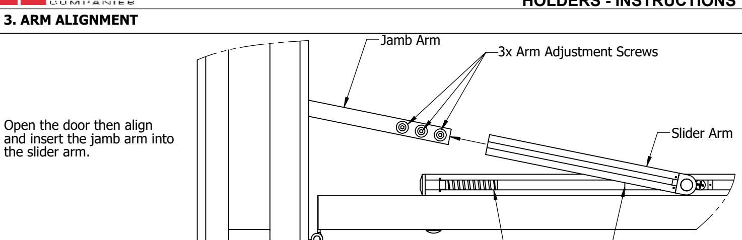
End Cap Spring Stop Jamb Bracket Jamb Arm Slider Arm Main Body 1. PARTS Screw Chart
| HARDWAWRE | QTY | Screw type | ||||
| Jamb | 4 | #14 x 1-1/2" FPHWS | ||||
| 4 | 1/4-20 x 5/8" FPHMS | |||||
| Door | 2 | 5/16"-18 x1-1/2" FPHMS | ||||
| 2 | 5/16"-18 x 1-9/16" THRU BOLT | |||||
| Arm | 3 | 5/16"-18 x 5/16" HBHFS | ||||
| 1 | 5/32" HEX KEY | |||||
Pre Installation Notes:
- 1. Hollow metal frames must be properly reinforced with 3/16" [5] thick plates that are at least 12" [305] long.
- 2. Hollow metal doors must be properly reinforced with 3/16" [5] thick plates that are at least 2-1/2" [64] wide.
- 3. Hold open(7017) and Friction(7015) are not permitted for use on fire doors.
- 4. Stop only(7016) is subject to job specification for fire door use.
2. INSTALL OVERHEAD DOOR HOLDER/STOP (ODHS) (Right Hand Shown)
| 85-95 degree of opening | 96-110 degree of opening | |||||
|---|---|---|---|---|---|---|
| ODHS Size | Door Width | А | В | А | В | С |
| 7000 SZ1 | 24"-30" | 1-3/8" [34.9] | 7" [177.8] | 1-3/8" [34.9] | 7" [177.8] | 20-3/4" [527] |
| 31"-40" | 6" [152.4] | 5" [127] | ||||
| 7000 SZ2 | 41"-45" | 11-1/2" [292.1] | 11" [279.4] | 10" [254] | 10" [254] | 25-13/16" [655.6] |
| 46"-55" | 16" [406.4] | 14-1/2" [368.3] | ||||
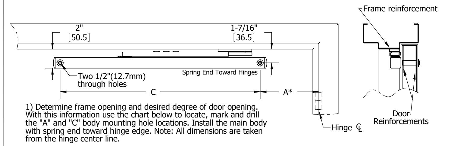
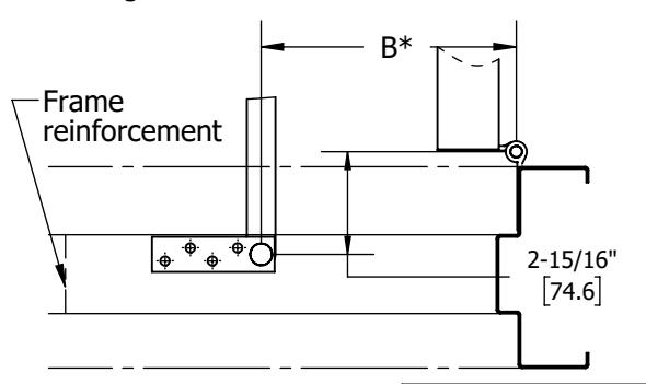
2) Locate and mark desired dimension "B" from the chart above. Cut out the "Jamb Bracket Template" from the bottom of the page and align on frame to locate and drill the four jamb bracket mounting holes. Install the jamb bracket. Note: All dimensions are taken from the hinge center line.
All dimensions are in inches and [mm]
3-1/2" 88.9 1" 25.4 3/8" 9.5 23/32" 18.3 5/8" 16 23/32" 18.3 11/16" 17.5 5/16" 7.9 4X 9/32" 6.8 Cut out and tape parallel to the frame at the "B" measurement from step 2. Hinge Side B Jamb Bracket Template
DRAWING NO: I-CL00316 REV:05 SHEET 1 OF 2 HAGER COMPANIES 139 Victor Street, St. Louis, MO 63104 - (800) 325-9995 - Fax (800) 782-0149

4. SETTING DESIRED DOOR OPENING
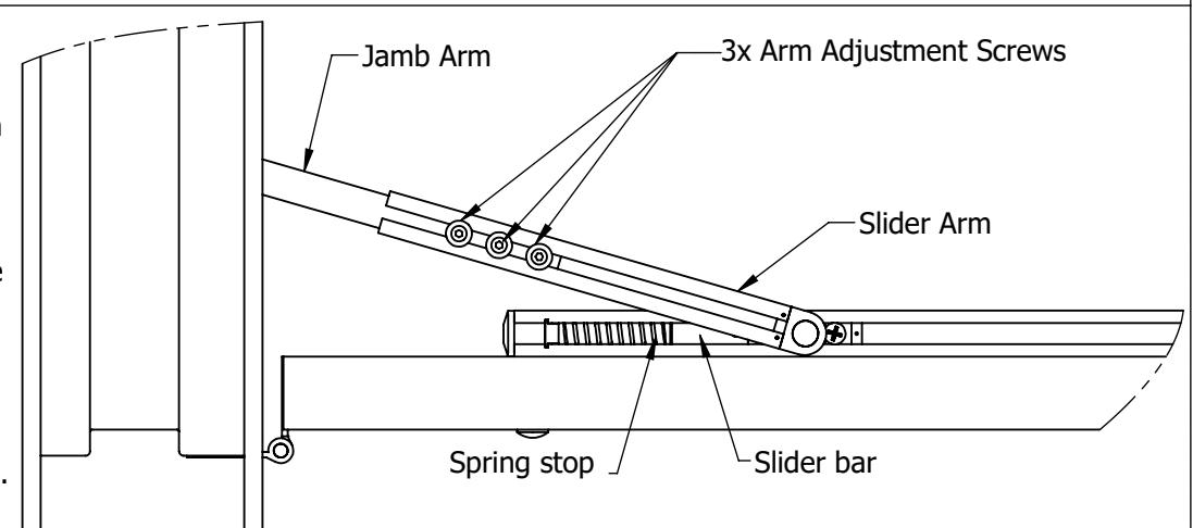
If it applies, disengage the hold open engagement switch (step 5a). With the door held at the desired maximum opening angle, position the slider bar against the stop spring. Then tighten the three friction arm screws to 12 ft-lbs [16.3 Nm]
If dead stop is required, position the door 5-7 degrees less then the desired dead stop and tighten as instructed.
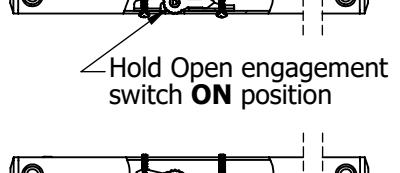
Hold Open engagement switch OFF position
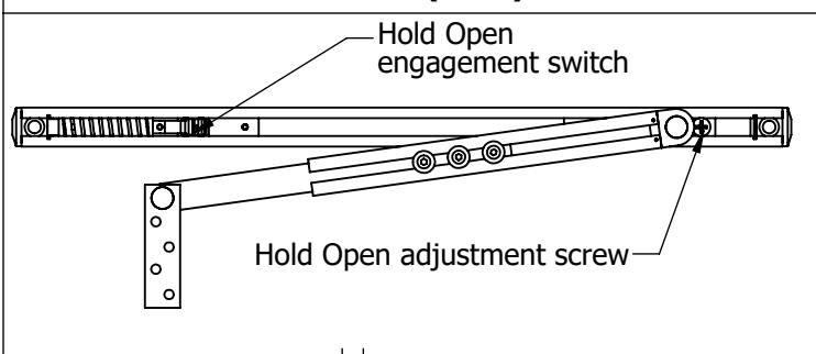
Using a Philips screwdriver, turn the hold open adjustment screw clockwise to increase the holdopen tension and counter-clockwise to lower the tension.
5a. OPTIONAL HOLD OPEN (7017) 5b. OPTIONAL FRICTION HOLD OPEN (7015)
Spring stop Slider bar
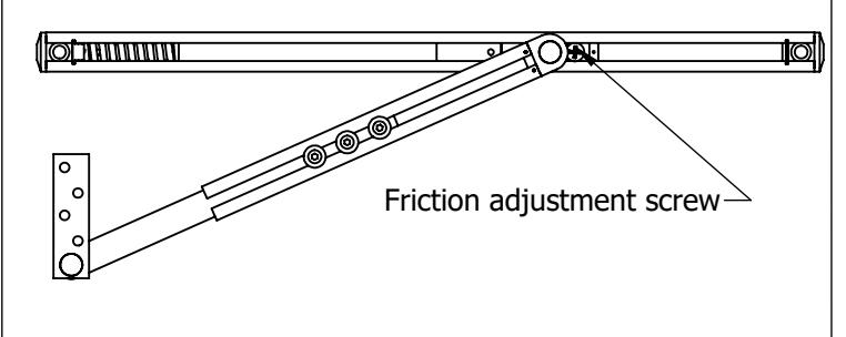
Using a flat head screwdriver, turn the friction adjustment screw clockwise to increase the friction and counterclockwise to lower the friction.
DRAWING NO: I-CL00316 REV:05 SHEET 2 OF 2