7000 & 12-7000 SERIES INSTRUCTIONS
Open the original PDF document
View PDFInstructions for Installing 7000 & 12-7000 Series Concealed Vertical Rod Latch Device

- Note 1) Measure gap between top of door/ frame and bottom of door and floor before removing door from hinges (Ref. Steps 6 & 7).
- Note 2) For 100 Series Auxiliary Controls: Prep door BEFORE installing latching device. Install Aux Control AFTER installing latching device.
For 106 or 113 Aux Controls: Template: 4212 Installation instructions: A5985
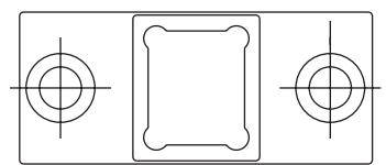
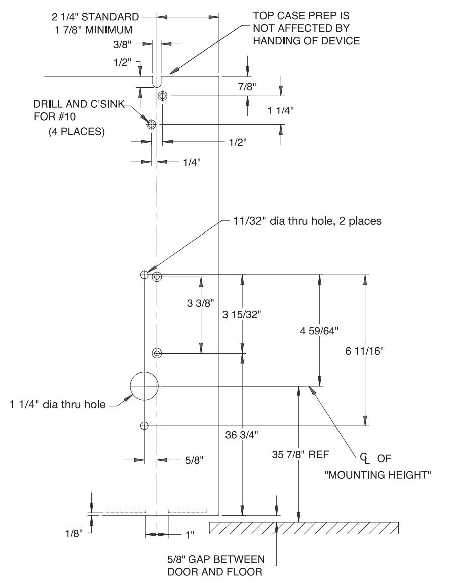
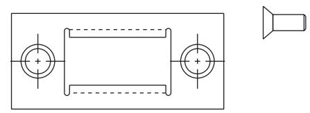
1) Drill and countersink door per templates to right and below.
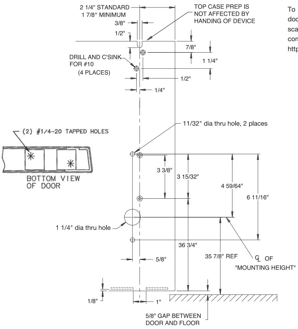
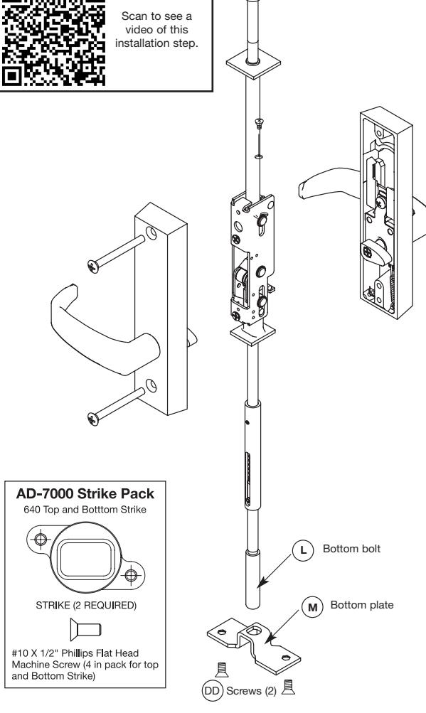
To view the QR Code video clips within this document, download a free mobile app and scan the QR Code with your mobile device. The complete video can be viewed on YouTube at https://youtu.be/IC8KQeXHCG4


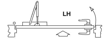
Left Hand Door
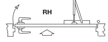
Right Hand Door
PAGE 1
SARGENT
ASSA ABLOY
video of this
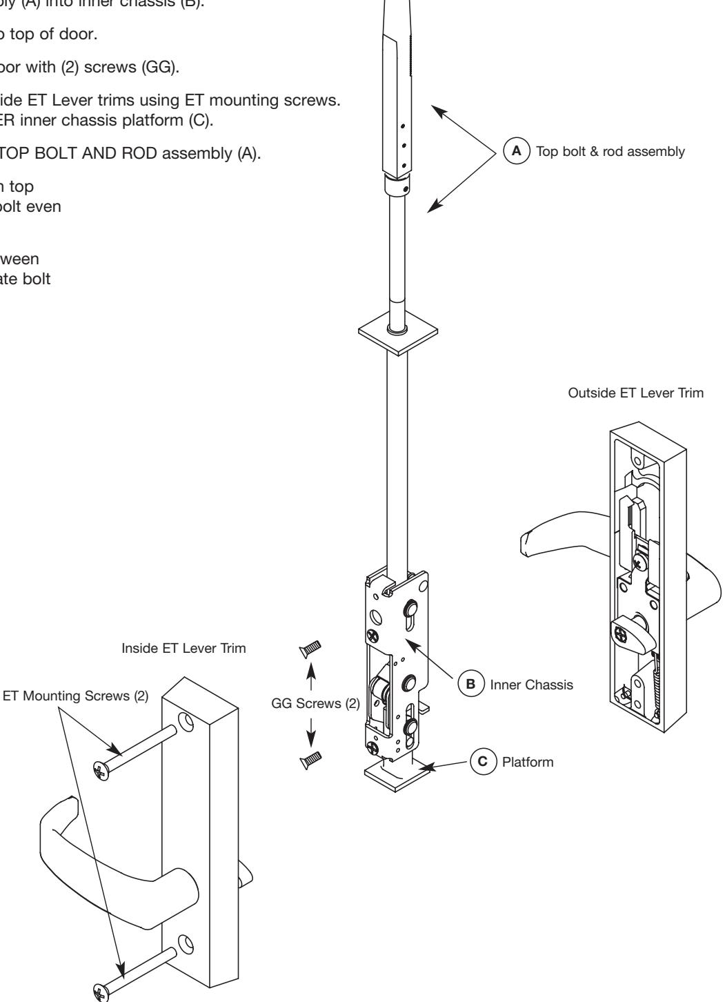
- Screw top bolt & rod assembly (A) and bottom bolt & rod assembly (D) into inner chassis (B).
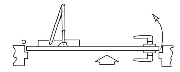
- 3) Slide complete assembly into top of door.
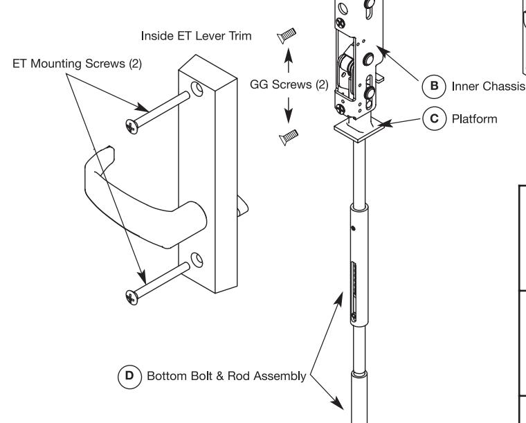
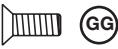
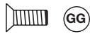
- 4) Attach inner chassis (B) to door with (2) screws (GG).
- Attach inside and outside ET Lever trims using ET mounting screws. Insert spindle thru 1-1/4" thru hole. Spindle cams must be UNDER inner chassis platform (C).
- 6) Adjust TOP BOLT AND ROD assembly (A) with the inside lever rotated in a down position.
For 1/8" GAP OR LESS between top of door and door frame, rotate bolt even with top of door.
For 1/8" GAP OR GREATER between top of door and door frame, rotate bolt to gap minus 1/8" above door.
Bottom case mounting screw (1/4"-20 x 1/2" Phillips flat head machine screw 2 pcs) [not used with nb prefix]
Spindle cam
(2) Inner chassis screws & (2) top strike screws (# 10-24 x 1/2" Phillips flat head machine screws, 4 pcs)

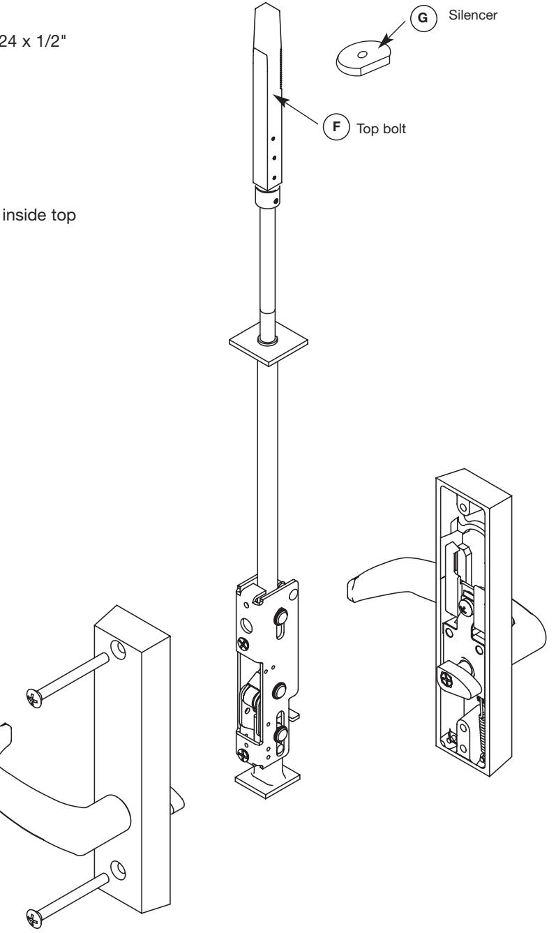
A) Top bolt & rod assembly
Outside ET Lever Trim

Top case mounting screw (#10-24 x 3/8" Phillips oval head machine screw 2 pcs)
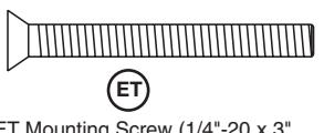
ET Mounting Screw (1/4"-20 x 3" Phillips oval head mach.screw 2 pcs)
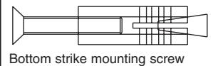
Bottom strike mounting screw (2) 1/4-20 x 2 Phillips head machine screws and (2) anchor nuts
Adjust BOTTOM BOLT AND ROD assembly (D) with the inside lever rotated in a down position.
For 1/8" GAP OR LESS between door bottom and high point of floor, rotate bolt to make even with bottom of door.
For 1/8" GAP OR GREATER between door bottom and high point of floor, rotate bolt to gap minus 1/8" below door.
PAGE 2
SARGENT
ASSA ABLOY
E Top case
G Silencer
8) Slide rod silencer (G) over top bolt (F) onto rod. NOTE: The teeth on the rod should face the teeth on the top case.
- 9) SLIDE TOP case (E) over top bolt (F). Secure with (2) screws (HH).
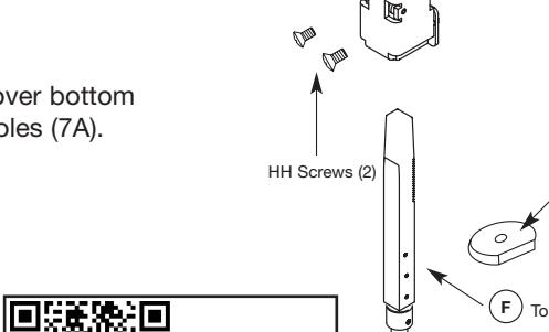
- For AD-7000 bottom bolt: Install bottom plate (M) over bottom bolt (L) and secure with (2) screws (HH) using holes (6A).
For AD-7000 Bottom Bolt Install bottom plate (M) over the Bottom bottom bolt (L) and secure with two Plate #10-24 x 3/8" oval head screws (DD) Bottom bolt using holes (6A) #10-24 x 3/8" Oval Head Screws
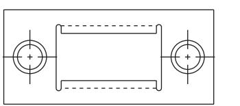
For MD-7000 & 12-MD-7000: Install bottom plate (M) over bottom 10B) bolt (L) and secure with (2) screws (DD) using tapped holes (7A).
video of this installation step.
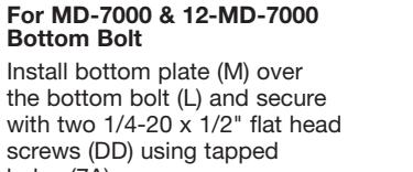
(L) Bottom 1/4-20 x 1/2" flat head screw
11) Install door into the frame using hinges.
12) 650 Top Strike
Bottom Bolt
holes (7A)
screws (DD) using tapped
ATTACH 650 Top Strike to door frame, (2) #10-24 x 1/2" flat head screws (Reference template 4449).
13) 606 Bottom Strike
Attach 606 Bottom Strike to floor under bottom bolt,
- (2) 1/4 20 x 2 Phillips head machine screws and
- (2) anchor nuts (Reference template 4449).
14) BEFORE CLOSING DOOR
Adjust bolts per steps 6 & 7 as needed:
- a) Either lever retracts both bolts.
- b) Bolts stay retracted (hold back).
- c) Bolts release when door closes; button inside top of door hits frame.
- d) Bolts engage strikes, 1/4"-5/16".
Instructions for Installing NB-7000 & 12-NB-7000 Series Concealed Vertical Rod Latch Device

- Note 1) Measure gap between top of door and frame, and bottom of door and floor before removing door from hinges. (Ref. Step 6 & 7).
- Note 2) For 100 Series Auxiliary Controls: Prep door BEFORE installing latching device. Install Aux Control AFTER installing latching device.
- Note 3) For 100 Series Auxiliary Controls: Prep door BEFORE installing latching device. Install Aux Control AFTER installing latching device. For 106 or 113 Aux Controls: Template 4212; Installation instructions A5985.
- 1) Drill and countersink door per template.
Handing
Left Hand Door
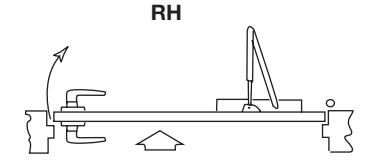
Right Hand Door
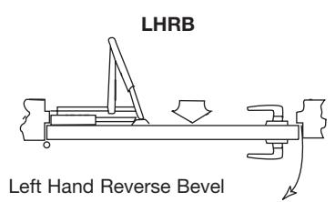
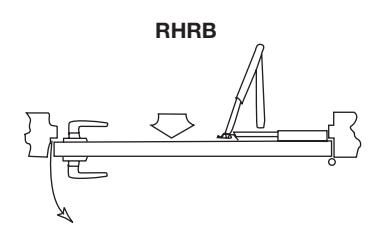
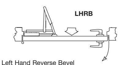
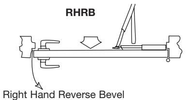
Right Hand Reverse Bevel
SARGENT
ASSA ABLOY
- 2) Screw top bolt & rod assembly (A) into inner chassis (B).
- 3) Slide complete assembly into top of door.
- 4) Attach inner chassis (B) to door with (2) screws (GG).
- 5) Through bolt inside and outside ET Lever trims using ET mounting screws. Spindle cams must be UNDER inner chassis platform (C).
- 6) USE INSIDE TRIM to adjust TOP BOLT AND ROD assembly (A).
For 1/8" GAP OR LESS between top of door and door frame, rotate bolt even with top of door.
For 1/8" GAP OR GREATER between top of door and door frame, rotate bolt to gap minus 1/8" above door.
Chassis mounting screw metal door application (#10-24 x 3/4" Phillips flat head mach. screws, 4 pcs)
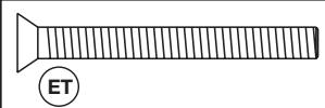
ET Mounting Screw (1/4"-20 x 3" Phillips oval head mach. screws 2 pcs)

Top case mounting screw (#10-24 x 3/8" Phillips oval head machine screw 2 pcs)
PAGE 5
E Top case
- 7) Slide rod silencer (G) over top bolt (F) onto rod. Position top case (E) over top bolt (F). Secure top case (E) to door with (2) screws (HH).
- 8) Install door in frame using hinges.
- 8) 650 Top Strike ATTACH 650 Top Strike to door frame, (2) #10-24 x 1/2" flat head screws (Reference template 4449).
-
9) BEFORE CLOSING DOOR Adjust bolts per step 6 as needed:
- a) Either lever retracts bolt.
- b) Bolt stays retracted (hold back).
- c) Bolt releases when door closes; button inside top of door hits frame.
- d) Bolt engages strike, 1/4"- 5/16".
HH Screws (2)

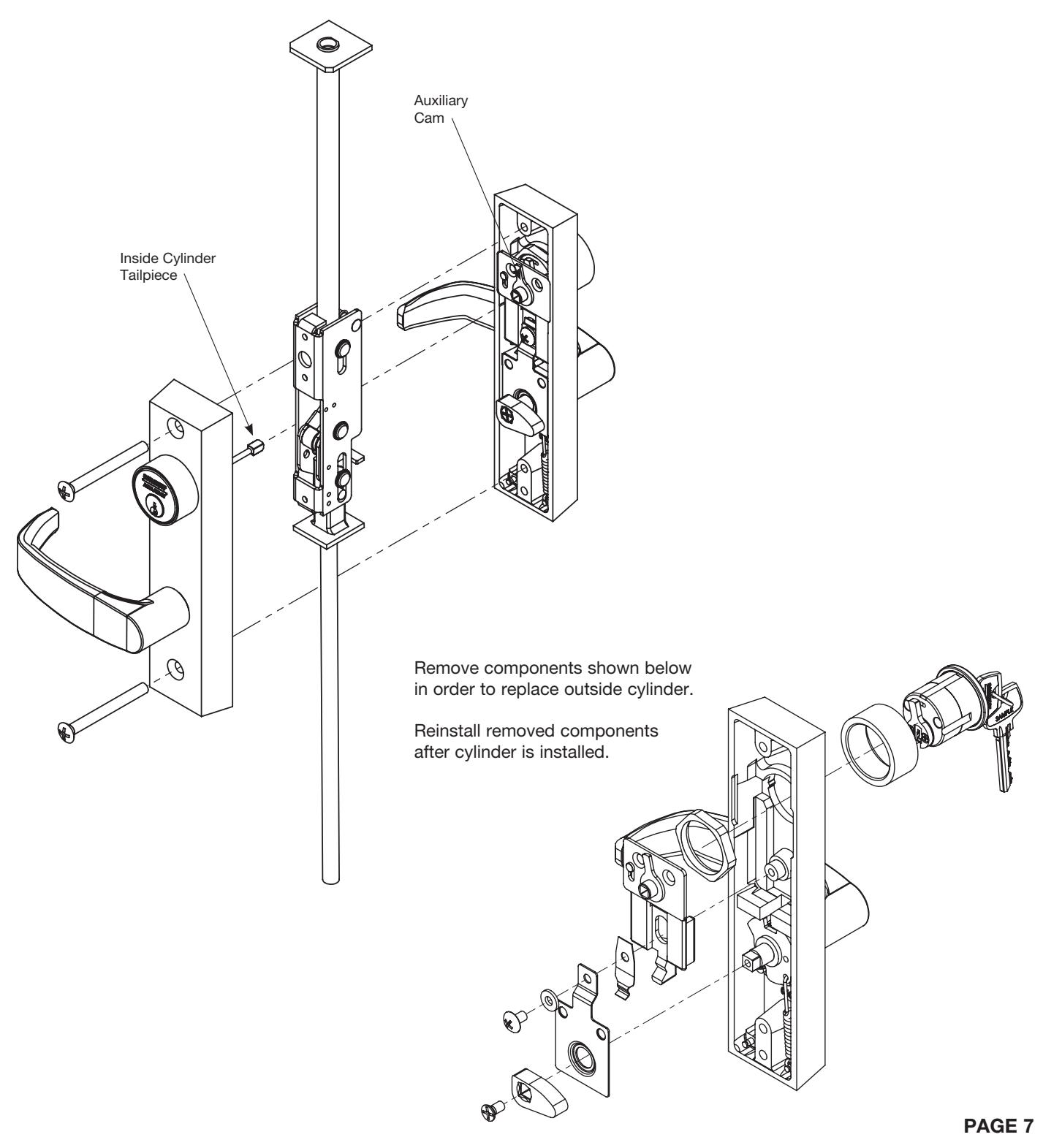
Instructions for Installing Classroom Function on 7000,12-7000, NB-7000 and 12-NB-7000 Series Concealed Vertical Rod Latch Device

- 1. Through bolt the trim as described in Step 5 on pages 1 & 2. Ensure that the inside cylinder tailpiece engages the auxiliary cam on the outside trim.
- 2. Check for smooth locking and unlocking via cylinder on both sides of the door.

SARGENT Manufacturing Company 100 Sargent Drive New Haven, CT 06511 USA 800-727-5477 • www.sargentlock.com
Founded in the early 1800s, SARGENT® is a market leader in locksets, cylinders, door closers, exit devices, electro-mechanical products and access control systems for new construction, renovation, and replacement applications. The company's customer base includes commercial construction, institutional, and industrial markets.
Copyright © 2017, Sargent Manufacturing Company, an ASSA ABLOY Group company. All rights reserved. Reproduction in whole or in part without the express written permission of Sargent Manufacturing Company is prohibited.