6830 Series Template
Open the original PDF document
View PDF6830 SERIES LOW PROFILE WITH REVERSE LATCH

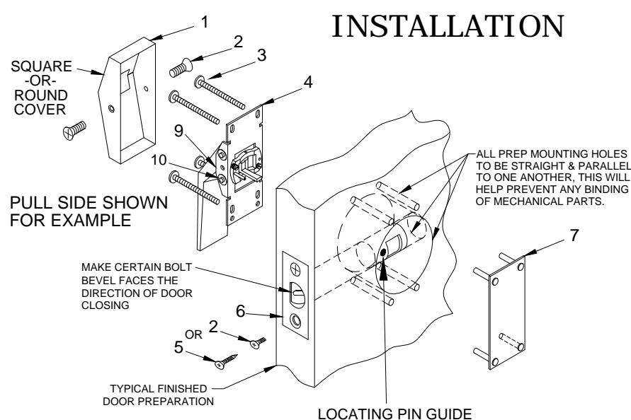
| ITEM | QTY | PART DESCRIPTION |
| 1 | 1 | COVER |
| 2 | 4 | 8-32 x 3/8" FHMS |
| 3 | 4 | 10-32 x 1-1/2" PH. PN. HD. M.S. |
| 4 | 1 | PULL OR PUSH SIDE HANDLE ASSY |
| 5 | 2 | #8 x 3/4" PH. FL. HD. W.S. |
| 6 | 1 | LATCH |
| 7 | 1 | EXIT ONLY PLATE |
| 8 | ||
| 9 | REF | HANDLE SPRING |
| 10 | REF | PIN & RETAINING WASHER |
INSTALLATION INSTRUCTIONS:
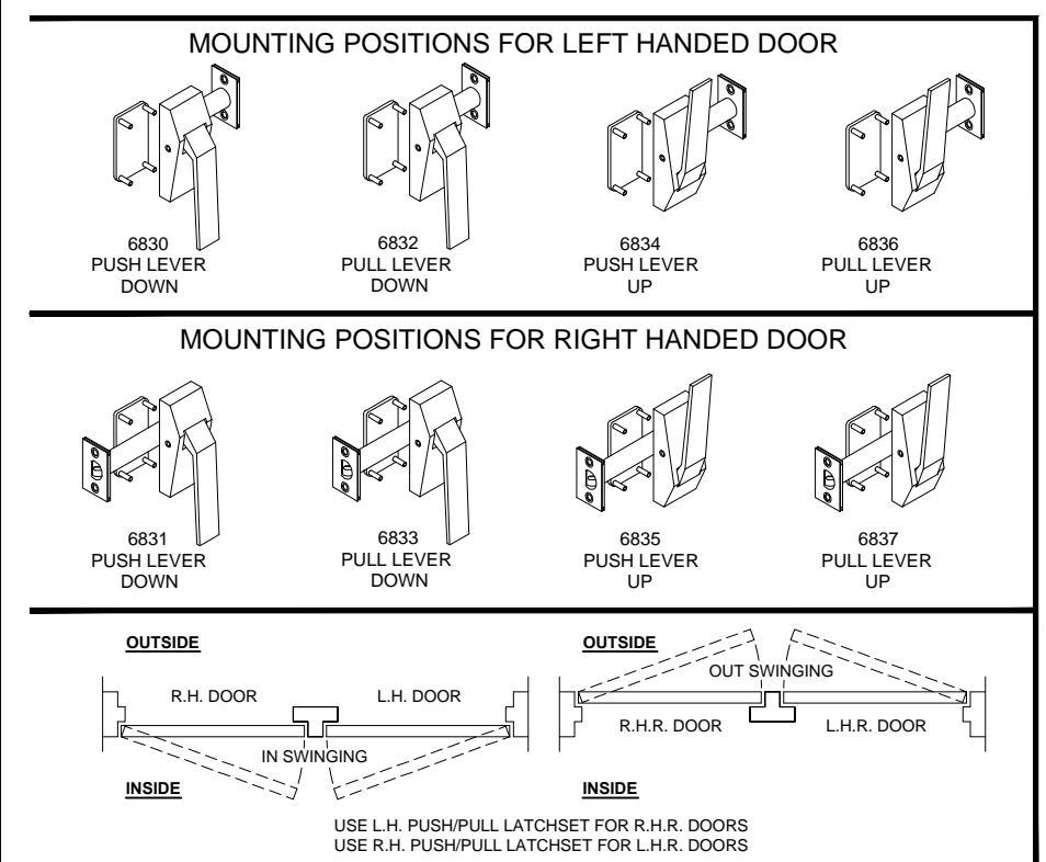
- 1. Push/Pull latches are assembled for right hand and left hand doors. Be sure correct side matches door application.
- 2. Place latch bolt (item 6) unit in door making sure bolt bevel faces direction of door closing. Attach latch with two (2) #8 or 8-32 (item 2 or 5) screws depending on door.
- 3. Position lever assembly so that locating pin and cam arm enter into corresponding holes in latch bolt unit. Attach lever assembly (item 4) by thru bolting onto exit only plate (item 7) with four (4) #10-32 M.S. (item 3) For purpose of alignment do not tighten screws until all four (4) screws have been started.
- 4. Apply covers and fasten with (2) 8-32 (item 2) for each cover.
- 5. Insert dust box in frame mortise and attach strike with two (2) #8 or 8-32 screws.
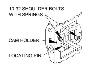
TO CHANGE HANDING DIRECTION OF PUSH OR PULL LEVER
Remove the (2) 10-32 shoulder bolt with spring that secure the cam holder assembly, Note the direction of the locating pin before starting. Rotate the cam holder assembly 180°. Reinstall the (2) 10-32 shoulder bolt with springs.
PATENT PENDING
6830-1-06.DWG
H
www.abhmfg.com
E-mail: abhinfo@abhmfg.com Architectural Builders Hardware Mfg., Inc. 1222 Ardmore Ave., Itasca, IL 60143 630.875.9900; FAX 800.9FAXABH (932.9224)
© 2017 ABH Mfg., Inc. printed in USA REVI
6830 PAGE 1 OF 3 REVISED 05-19-17
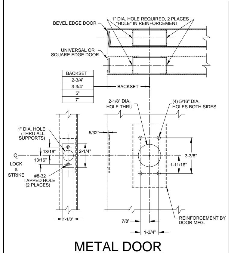
6830 SERIES LOW PROFILE - DOOR PREP
(VERTICAL MOUNTING SHOWN)
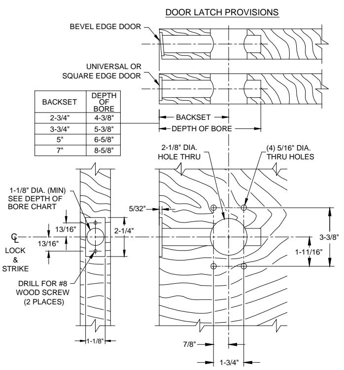
WOOD DOOR
(VERTICAL MOUNTING SHOWN)
DOOR PREP INFORMATION:
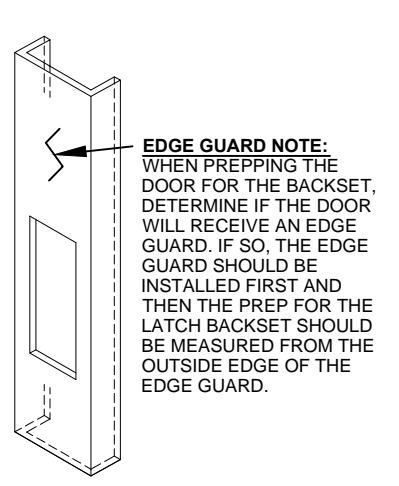
- 1. BACKSET DIMENSION FROM LOW EDGE OF BEVEL.
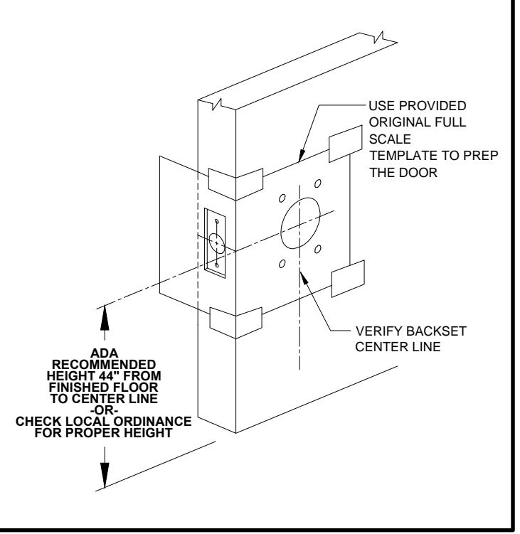
- 2. CENTER PUNCH ALL HOLES.
- 3. DRILL HOLES (FOR HOLLOW METAL DOORS, DO NOT DRILL THRU. CENTER PUNCH & DRILL HOLES FROM BOTH SIDES OF DOOR).
6830-2-06.DWG
6830 PAGE 2 OF 3 REVISED 05-19-17

@ www.abhmfg.com E-mail: abhinfo@abhmfg.com Architectural Builders Hardware Mfg., Inc. 1222 Ardmore Ave., Itasca, IL 60143 630.875.9900; FAX 800.9FAXABH (932.9224)
© 2017 ABH Mfg., Inc. printed in USA
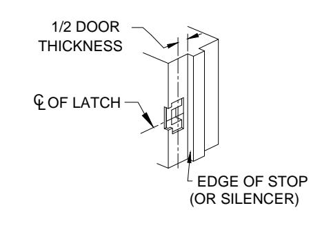
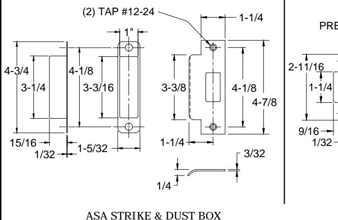
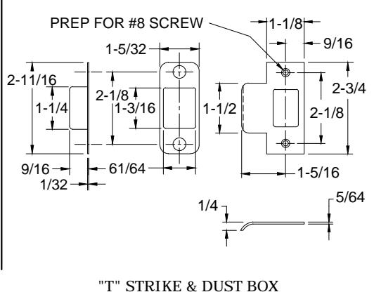
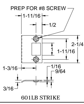
6830 SERIES LOW PROFILE - FRAME PREP REINFORCEMENT BY FRAME MFG. G LOCK & STRIKE HALF DOOR THICKNESS DOOR STOP (MEASURED FROM STOP OF 1-1/4" SILENCER WHEN USED) +1/64 -0 MORTAR #12-24 GUARD TAPPED HOLE (2 PLACES) 4-7/8 3-3/8" (MIN) +1/64 LOCK & STRIKE 2-1/16 METAL FRAME (ASA STRIKE SHOWN FOR EXAMPLE)
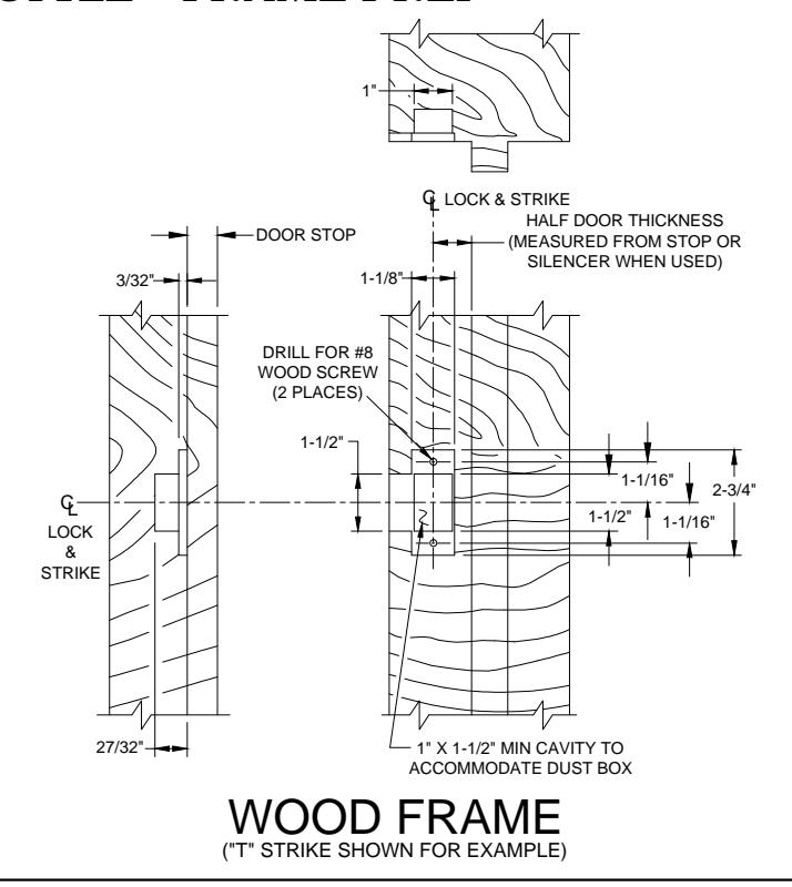
FRAME PREP:
- 1. Mark centerline of latch bolt on frame.
- 2. Center strike and mark screw positions.
- 3. Mortise to required strike and box depth.
- 4. All dimensions in inches.
6830-3-06.DWG

E-mail: abhinfo@abhmfg.com Architectural Builders Hardware Mfg., Inc. 1222 Ardmore Ave., Itasca, IL 60143 630.875.9900; FAX 800.9FAXABH (932.9224)
© 2017 ABH Mfg., Inc. printed in USA
PAGE 3 OF 3 REVISED 05-19-17