6800 Series Template – Low Profile Cylindrical Push Pull Latch Template
Open the original PDF document
View PDF6800 SERIES LOW PROFILE INSTALLATION

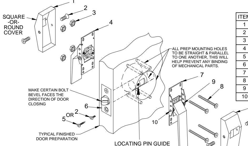
| ITEM | QTY | PART DESCRIPTION |
|---|---|---|
| 1 | 2 | COVER |
| 2 | 6 | 8-32 x 3/8" FHMS |
| 3 | 4 | 12-24 NUT W/ NYLON WASHER |
| 4 | 1 | PULL SIDE HANDLE ASSEMBLY |
| 5 | 2 | #8 x 3/4" PH. FL. HD. W.S. |
| 6 | 1 | LATCH |
| 7 | 1 | PUSH SIDE HANDLE ASSEMBLY |
| 8 | 4 | 12-24 x 2-3/8" PH. TRUSS HD. M.S. |
| 9 | REF | HANDLE SPRING |
| 10 | REF | PIN & RETAINING WASHER |
INSTALLATION INSTRUCTIONS:
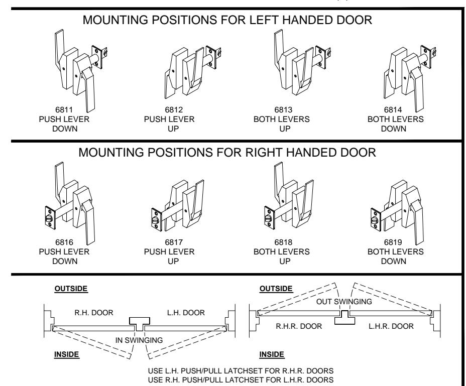
- 1. Push/Pull latches are assembled for right hand and left hand doors. Be sure correct side matches door application.
- 2. Place latch bolt (item 6) unit in door making sure bolt bevel faces direction of door closing. Attach latch with two (2) #8 or 8-32 (item 5 or 2) screws depending on door.
- 3. Position lever assemblies so that locating pin and cam arm enter into corresponding holes in latch bolt unit. Attach lever assemblies (item 4 & 7) by thru bolting onto door with four (4) #12-24 (item 8) screws and four (4) #12-24 (item 3) kep nuts. For purpose of alignment do not tighten screws until all four (4) screws have been started.
- 4. Apply covers and fasten with (2) 8-32 screws (item 2) for each cover.
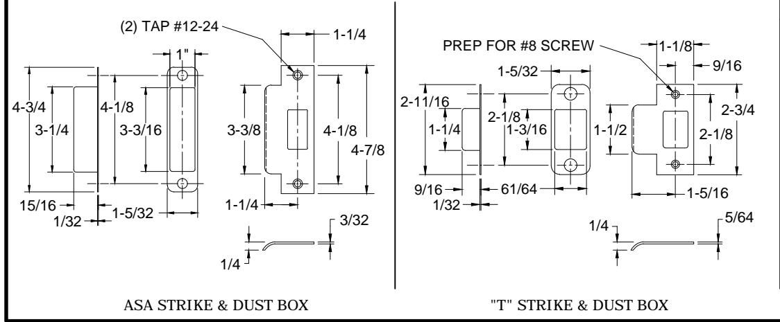
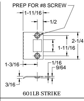
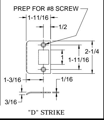
- 5. Insert dust box in frame mortise and attach strike with two (2) #8 or 8-32 screws.
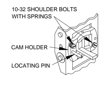
TO CHANGE HANDING DIRECTION OF PUSH OR PULL LEVER
Remove the (2) 10-32 shoulder bolt with spring that secure the cam holder assembly, Note the direction of the locating pin before starting. Rotate the cam holder assembly 180°. Reinstall the (2) 10-32 shoulder bolt with springs.
PATENT PENDING
6800-1-10.DWG
A :H
www.abhmfg.com E-mail: abhinfo@abhmfg.com Architectural Builders Hardware Mfg., Inc. 1222 Ardmore Ave., Itasca, IL 60143 630.875.9900; FAX 800.9FAXABH (932.9224)
© 2019 ABH Mfg., Inc. printed in USA
PAGE 1 OF 3 REVISED 06-10-19
6800 SERIES LOW PROFILE - DOOR PREP
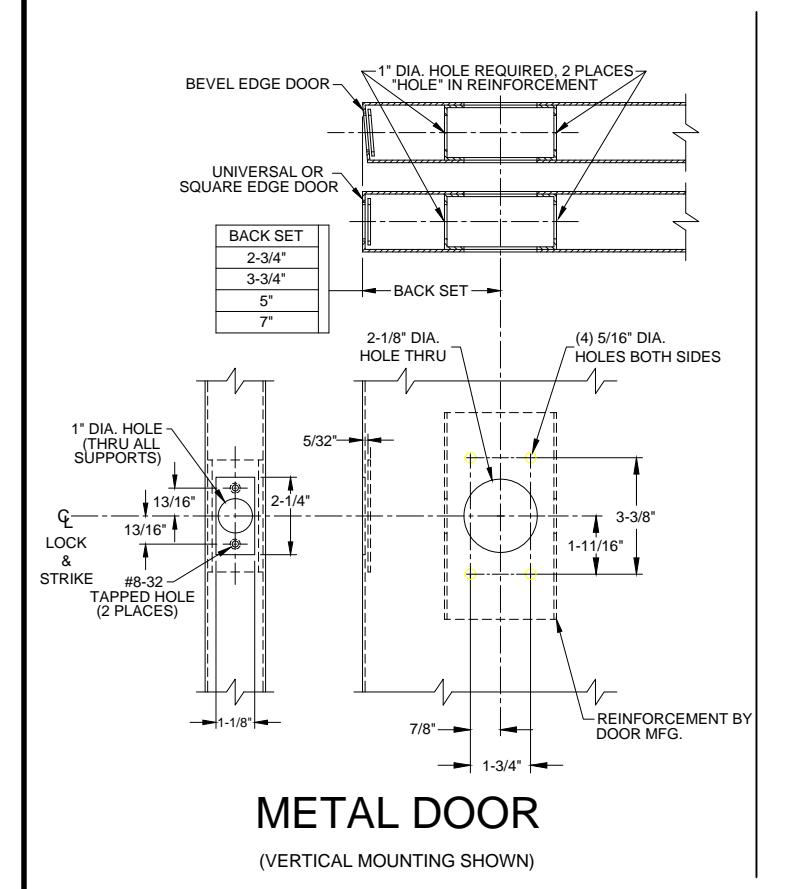
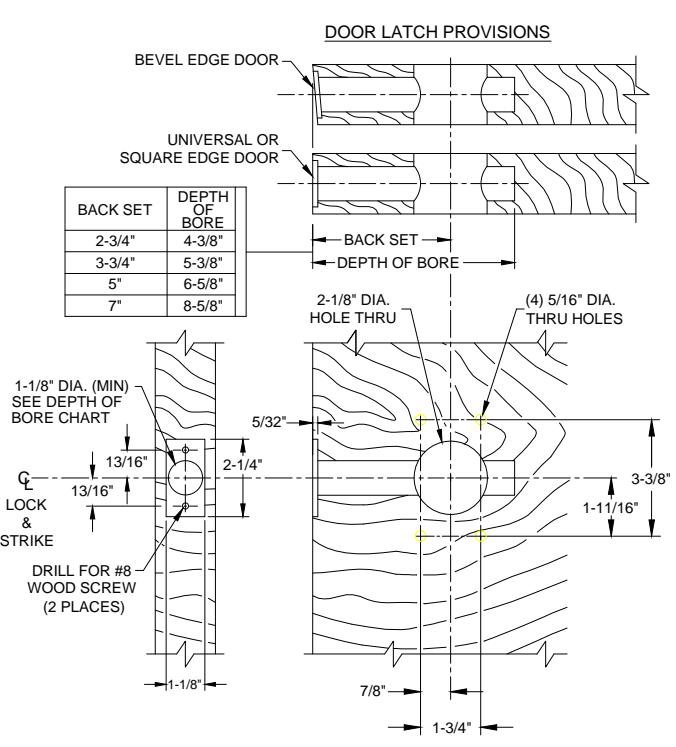
WOOD DOOR
(VERTICAL MOUNTING SHOWN)
DOOR PREP INFORMATION:
- 1. BACKSET DIMENSION FROM LOW EDGE OF BEVEL.
- 2. CENTER PUNCH ALL HOLES.
- 3. DRILL HOLES (FOR HOLLOW METAL DOORS, DO NOT DRILL THRU. CENTER PUNCH & DRILL HOLES FROM BOTH SIDES OF DOOR).

www.abhmfg.com E-mail: abhinfo@abhmfg.com Architectural Builders Hardware Mfg., Inc. 1222 Ardmore Ave., Itasca, IL 60143 630.875.9900; FAX 800.9FAXABH (932.9224)
© 2019 ABH Mfg., Inc. printed in USA
6800 PAGE 2 OF 3 REVISED 06-10-19
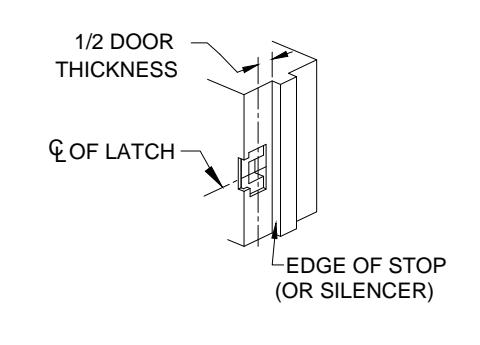
6800 SERIES LOW PROFILE - FRAME PREP REINFORCEMENT BY FRAME MFG. G LOCK & STRIKE HALF DOOR THICKNESS DOOR STOP (MEASURED FROM STOP OF 1-1/4" SILENCER WHEN USED) +1/64 -0 MORTAR #12-24 GUARD TAPPED HOLE (2 PLACES) 4-7/8 3-3/8 (MIN) +1/64 LOCK & STRIKE 2-1/16 METAL FRAME (ASA STRIKE SHOWN FOR EXAMPLE)
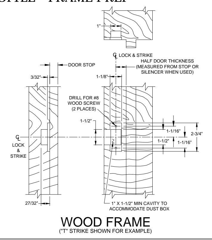
FRAME PREP:
- 1. Mark centerline of latch bolt on frame.
- 2. Center strike and mark screw positions.
- 3. Mortise to required strike and box depth.
- 4. All dimensions in inches.
6800-3-10.DWG

® www.abhmfg.com
E-mail: abhinfo@abhmfg.com Architectural Builders Hardware Mfg., Inc. 1222 Ardmore Ave., Itasca, IL 60143 630.875.9900; FAX 800.9FAXABH (932.9224)
© 2019 ABH Mfg., Inc. printed in USA
PAGE 3 OF 3 REVISED 06-10-19