6700 B Series Asylum Trim Round Knob for Mortise Lock Template
Open the original PDF document
View PDF6700 "B" SERIES, ASYLUM TRIM ROUND KNOB INSTALLATION FOR MORTISE LOCK
ITEM
1
OTY
COVER

PART DESCRIPTION

- 1. TRIM CAN BE MOUNTED UP, DOWN, HORIZONTALLY. **
- 2. USES STANDARD MORTISE LOCK DOOR PREP.
- 3. MORTISE LOCK NOT PROVIDED.
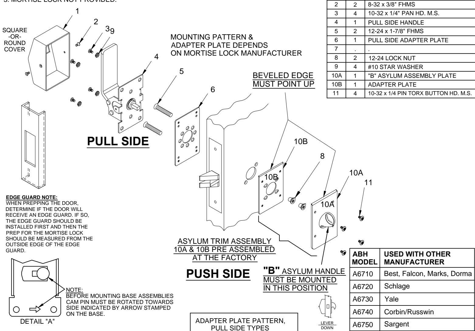
INSTALLATION INSTRUCTIONS:
- 1. Prep for lock body according to mortise lock manufacturer installation.
-
2. A) Place the pre-assembled asylum trim assembly 10A & 10B on the side of the door that will match the diagonal mortise lock mounting through holes.
- B) Then place pull side adapter plate (item 6) on outside of door and attach with (2) 12-24 screws (item 5). Do not over tighten.
-
3. Assemble trim:
- A) With trim in hand. Rotate the cam assembly until the cam pin stops on the appropriate side (See Detail "A").
- B) Place pull side handle on pull side of the door so that spindle engages with the mortise lock and fasten with (4) 10-32 screws (item 3) with (4) star washer (item 9). Test pull side handle (item 4) for latch retraction. If latch does not extend. Loosen both 12-24 screws (item 5) to adjust alignment.
- C) Test lock for proper operation.
- D) Place cover (item 1) over pull trim and secure with (2) 8-32 screws (item 2) on each side.
PATENT No. 6,196,599 & 5,730,478

R www.abhmfg.com
E-mail: abhinfo@abhmfg.com Architectural Builders Hardware Mfg., Inc. 1222 Ardmore Ave., Itasca, IL 60143 630.875.9900; FAX 800.9FAXABH (932.9224)
© 2017 ABH Mfg., Inc.
A6760
A6770
PDQ
Arrow Brand names are trademarks or registered trademarks of their respective companies
6700-B-00.DWG 6700-B PAGE 1 OF 1 ISSUED 02-03-17
printed in USA