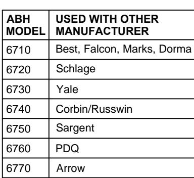
6700 B-AB Series Asylum Trim Round Knob on Both Sides for Mortise Lock Template
Open the original PDF document
View PDF6700-B-AB SERIES, ASYLUM TRIM ROUND KNOB INSTALLATION FOR MORTISE LOCK
NOTES
- 1. TRIM MUST BE MOUNTED VERTICALLY.
- 2. VISION LITE MUST BE AT LEAST 6" FROM CENTERLINE OF TRIM.
- 3. PREP DOOR PER OTHER MANUFACTURER'S MORTISE LOCK TEMPLATE.
- 4. MORTISE LOCK NOT PROVIDED.
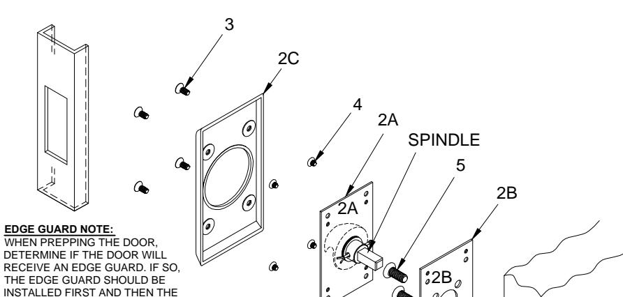
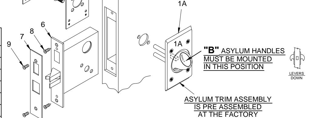
| ITEM | QTY | PART DESCRIPTION |
|---|---|---|
| 1A | 1 | "B" ASYLUM TRIM ASSEMBLY |
| 2A | 1 | "B" ASYLUM TRIM ASSEMBLY |
| 2B | 1 | ADAPTER PLATE |
| 2C | 1 | ASYLUM COVER |
| 3 | 8 | 8-32 x 1/4 PIN TORX FLAT HD. M.S. |
| 4 | 8 | 8-32 x 3/16 PHIL. FLAT HD. M.S. |
| 5 | 2 | 10-32 x 1/2" FHMS |
| 6 | 1 | MORTISE LOCK BY OTHERS |
| 7 | 1 | TRIM PLATE |
| 8 | 2 | 12-24 x 3/4" PH. F.H. COM. SCW. |
| 9 | 2 | 8-32 x 1/4" FHMS |
SHOULD BE MEASURED FROM THE OUTSIDE EDGE OF THE EDGE
GUARD.
Brand names are trademarks or registered trademarks of their respective companies
INSTALLATION INSTRUCTIONS:
- 1. Prep for lock body according to mortise lock manufacturer installation. Install mortise lock (item 6) using (2) 12-24 screws (item 8). Then mount the face plate (item 7) using (2) 8-32 screws (item 9).
-
2. A) Place the pre-assembled asylum trim assembly 1A on the side of the door that will match the diagonal mortise lock mounting through
- B) Place the adapter plate 2B centered with pre-assembled asylum trim assembly 1A while inserting the (2) mounting screws (item 5).
- C) After tightening the mounting screws (item 5) test lock and asylum trim assembly 1A for proper latch retraction and knob operation. If the latch does not extend / retract or if trim knob is binding, loosen 10-32 screws (item 5) and adjust alignment for proper operation and
- D) Place the asylum trim assembly 2A on the door so that spindle engages with the mortise lock and fasten with (4) 8-32 screws (item 4). Test the knob for latch retraction. If latch does not extend loosen both 10-32 screws (item 5) to readjust alignment and re-tighten.
- E) Place the asylum cover (item 2C) on the asylum trim assembly and screw together with (4) 8-32 screws (item 3).
PATENT No. 6,196,599 & 5,730,478

® www.abhmfg.com E-mail: abhinfo@abhmfg.com Architectural Builders Hardware Mfg., Inc. 1222 Ardmore Ave., Itasca, IL 60143 630.875.9900; FAX 800.9FAXABH (932.9224)
6700-B-AB PAGE 1 OF 1 ISSUFD 02-03-17
© 2017 ABH Mfg., Inc. printed in USA